If your school, or kids school, or other location relies on a central master clock that is broken, you may have a use for this device. New master clocks are available of course, but school budgets are under extreme pressures, and it really is a satisfying project if you have the necessary skills.
This master clock controls the signals sent to the slave clocks, and keeps them synchronized. The firmware in the clock currently supports the National Time synchronization protocol. The master clock also controls the bells that can be set at scheduled times during the day. The firmware in the clock currently supports two bell zones (indoor and outdoor bells).
The firmware in the clock also automatically adjusts to daylight savings time (this can be turned off). This library might also be useful for other clock-projects (make sure to also get the modified DateTime library).
The clock is set up by connecting it to a computer via the Arduino USB port, and running a Java control program with a GUI interface. Once the time has been set, and a bell schedule loaded, the computer can be disconnected.
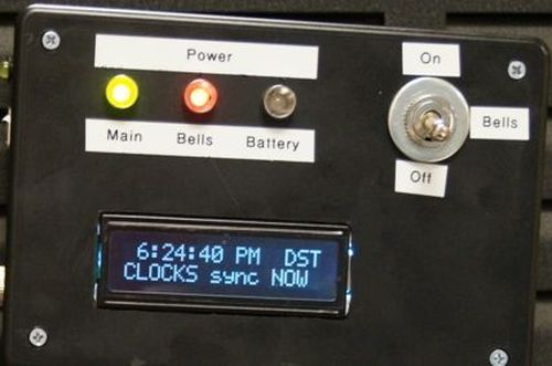
The design of the clock emphasizes simplicity, with a minimum of controls. Any complex setup is better handled by running the control program on a computer and temporarily connecting to the clock. The picture shows the front panel of the clock. The switch allows bells to be turned off completely if bells are not wanted (holidays, teacher training days etc.) The LEDs are normally all green, anything else indicates an unusual state.
Step 1: Find out about the master clock you are replacing
The master clock that was replaced by this project was a “Rauland 2490 Master Clock”. It had stopped working during a storm with heavy lightning. The slave clocks were moving very quickly (continuous synchronization signal), and the master clock was subsequently shut off.
Thus the clocks in the school all showed about the same time, but all wrong, and always wrong. This proves that the expression “even a broken clock is right two times a day” is false.
You will need to know:
* what protocol is used by the slave clocks (can probably guess based on the make of the clocks)
* how many zones are used for bells (indoor, outdoor, different buildings etc)
Your school (or other location) may even have documentation in the form of wiring diagrams. These can be very helpful when installing the new clock.
Step 2: You need these items
The picture shows some of the component you will need. You will need more. Please leave a note if I forgot something. Unfortunately, this instructable is constructed after the fact so I do not have all the pictures I would like.
* Arduino (or similar) with a Atmel ‘328 and a USB connection (the Duemilanove is perfect)
* 12v wall wart (say 250 mA, depends on the number of relays you will be driving)
* 9V battery, holder, and connector
* LED’s (one green, two red/green)
* diodes
* resistors
* relays (one for each bell zone, and one or more for the synchronization signal)
* LCD (standard 2×20 character HD44780-compatible display)
* suitable enclosures (large, medium, and small project boxes)
* plug and jack for power (5.5/2.1 mm for example)
* various screws and miscellaneous hardware
Computer with
* Arduino IDE installed (with the libraries needed, see step 5)
* the Java-based Master Clock Control program (and a Java runtime environment, and the rxtx library)
* USB port available
* USB cable for connecting to the Arduino
* time set to something reasonable
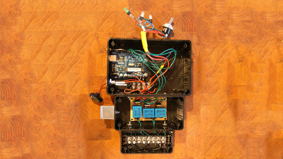
Step 3: Put it together the hardware
I used three project boxes
* one large box for the electronics
* one medium box for the relay circuits (a mix of low voltage and high voltage)
* one small box for the high voltage connections
Make holes in the boxes where screws can hold them together.
Also make holes where wires can go between the boxes.
The small box also needs holes where wires can be hooked up for installation.
The medium box needs a hole for attaching the 9V battery holder.
The large box needs holes for the USB connector of the Arduino and a hole for the power jack.
The lid/top of the large box also needs holes for the LEDs, the switch, and the LCD.
[box color=”#985D00″ bg=”#FFF8CB” font=”verdana” fontsize=”14 ” radius=”20 ” border=”#985D12″ float=”right” head=”Major Components in Project” headbg=”#FFEB70″ headcolor=”#985D00″]* Arduino (or similar) with a Atmel ‘328 and a USB connection
* 12v wall wart
* 9V battery, holder, and connector
* LED’s
* diodes
* resistors[/box]
For more detail: Arduino-based master clock for schools