If you’re like me, after I got my Arduino and performed a final programming on my first chip, I wanted to pull it off my Arduino Duemilanove and put it on my own circuit. This would also free up my Arduino for future projects.
The problem was that I’m such an electronics newbie that I didn’t know where to start. After reading through many web pages and forums, I was able to put together this Instructable. I wanted to have the information I learned all in one place, and easy to follow.
Comments and suggestions are welcome and appreciated as I’m still trying to learn all this stuff.
Edit:
Fellow Instructable member, Janw mentioned to me that it’s always a good idea to add a capacitor or 2 near your power. He mentioned using a couple of 100nF capacitors should work. I’m very grateful he pointed this out to me, because my first production circuit that I’m building upon this circuit, was having a little bit of strange behavior. So I hooked up one 10uF capacitor near my power, and it started behaving correctly! I don’t know why it didn’t affect my ‘blinking LED’ test, but I do know that I’m grateful for Janw for pointing this out to me. Thanks Janw.
Edit2:
Building upon the previous edit, I wanted to mention that Instructable member, kz1o brought out some more information regarding the capacitors. Please see his comment below, dated February 14th, 2010 @ 10:52 am.
Update – This Instructable is on Hack a Day!
Step 1: Parts needed
I bought my parts from Digikey and Sparkfun Electronics – they’re 2 of my favorite places to buy components. Anyway, here’s the list:
#1 – (Qty: 1) – ATMega328 chip with Arduino bootloader pre-installed ($5.50)
#2 – (Qty: 1) – 5VDC Switching power supply ($5.95)
(Note: If you don’t use a switching power supply, you must add in a voltage regulator and a couple of capacitors…see below)
#3 – (Qty: 2) – 22 pF ceramic disc capacitors ($.24 / ea)
#4 – (Qty: 1) – 16MHz Crystal ($1.50)
#5 – (Qty: 1) – Power jack ($.38) (Optional)
#6 – (Qty: 1) – Breadboard (hopefully you have one laying around, but if not, here’s one. ($8.73)
#7 – Small pieces of 22 awg solid wire. If you don’t have any, you can probably pick some up at your favorite electronics store.
Total cost for above before tax/shipping: about $14 (not including breadboard).
Alternatives / options:
Option / Alternative #1:
If you want to use an existing power supply you have around the house, make sure it is between 5V – 16V. If you are not sure if it is a regulated switching power supply, then you must use the following components too:
#1 option – (Qty: 1) – 5V Voltage Regulator (or another similar 5V voltage regulator) ($.57)
and
#1 option – (Qty: 2) – 10 uF Aluminum Capacitor ($.15 / ea)
(See below reference links for how to hook them up)
Option / Alternative #2:
If you don’t want to use standard items #3 and #4, you can replace those with:
#2 option – (Qty: 1) – 16 MHz Ceramic Resonator (w/cap) ($.54)
This part looks like a ceramic capacitor, and you hook the 2 outside pins up to where you would hook the crystal up (covered later in the Instructable), and the middle pin goes to ground. At least this is what I’ve read – I haven’t tried it yet. But as you may note, it is a little cheaper to go this route. 🙂
Ok, let’s start hooking stuff up!
Step 2: Hooking up power
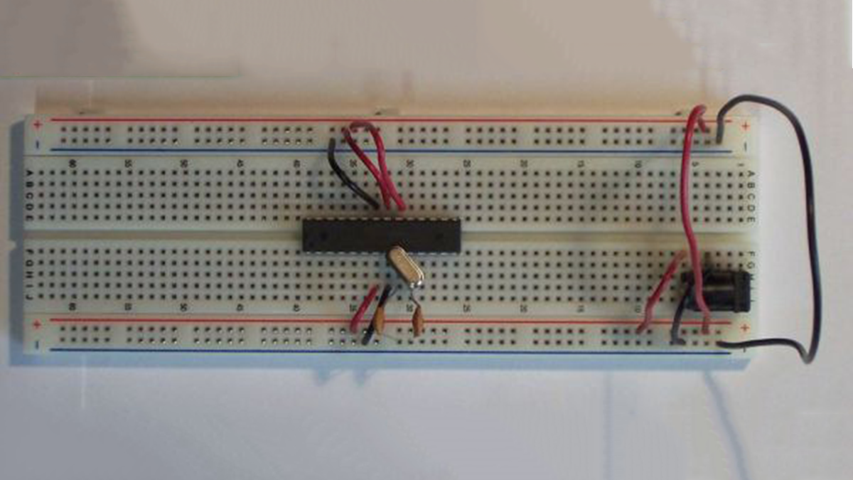
Go ahead and connect your power jack as shown in the first photo if you are using a power jack. Next, hookup a couple of wires as shown in the photo connecting the respective power (+ and -) rails together.
Step 3: Chip (microcontroller) placement
Now we want to put the microcontroller on your breadboard as shown in the photo. If this is a brand new chip, you have to bend both rows of pins in a little bit. What I do, is I hold the chip from both sides, and press the chip a little bit against a flat surface like a desk, and do this on both sides so that both sides are bent in equailly.
You most likely won’t have to do this if you’re pulling your chip from your Arduino – they’re already bent from being in the socket.
Please note the orientation of the chip – in the photos and for this Instructable, please place the chip so that the little half-round ‘notch’ is on the left.
Step 4: Bringing power to the chip
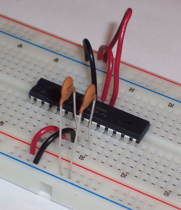
First hook up 3 wires as shown in the photo. One is going to be ground/negative (the black wire shown), and 2 will be to the positive.
If you can’t tell which pins are being connected on the chip, look at the 5th image in this step which is a pin mapping that I pulled from Arduino’s website to reference. Going by that, you can see that our ground/negative (black) wire is going to pin 22, and the 2 positives (the red wires) are going to pins 20 and 21.
Next hook up 1 more positive (red) wire and 1 more negative (black) wire as shown in the 3rd/4th photos (they’re the same thing…just one is zoomed in more).
Again, if you can’t tell, look at the Arduino mapping, and you can see that we’re connecting our ground/negative (black) wire to pin 8, and the positive (red) wire to pin 7.
[box color=”#985D00″ bg=”#FFF8CB” font=”verdana” fontsize=”14 ” radius=”20 ” border=”#985D12″ float=”right” head=”Major Components in Project” headbg=”#FFEB70″ headcolor=”#985D00″] ATMega328 chip with Arduino bootloader pre-installed
5VDC Switching power supply
22 pF ceramic disc capacitors
16MHz Crystal[/box]
For more detail: Standalone Arduino chip on breadboard