In this project, we are going to build a color sensor circuit with an Arduino microcontroller.
A color sensor is a device that can detect and differentiate between certain primary colors.
This sensor can detect and differentiate between the colors white, blue, green, and red.
<p “>A color sensor is actually a very useful device. Now in the age where autonomous vehicles are being developed that can run on their own, driverless cars, there has to be a way to be able to detect colors at places such as red stop signs and of course traffic lights, green to go and red to stop.
Another device that a color sensor can be integrated to is robotics. The more capabilities a robot has, the smarter it is. If a robot can differentiate colors, it has much greater capability. Imagine if you have a robot that can tell the difference between a green towel and a red towel. If you know you have a green towel and another person has a red towel, the robot can sort it appropriately.
Other applications include strip reading, ambient light sensing and calibration, and color matching.
So there’s no shortage of devices that a color sensor can be used in. Knowing how to use one is very useful, especially in this robotic, autonomous day in age.
In this circuit, we will make a device that can detect between white, bliue, green, and red.
Components
- TCS3200 Color Sensor
- Arduino
The TCS3200 functions as a color sensor. Its more specific title is a color light-to-frequency converter.
What this means is the sensor takes light and converts it into certain amount of current. This current is then fed into a frequency converter. The amount of current that is produced, which corresponds with the color of the light, produces a certain frequency. This output frequency then determines the color that was sensed. So basically the light is converted into a frequency. Each color has its own unique frequency. So this is how this sensor can differentiate between colors. Red has its unique frequency. Blue has its own. And so does every other color.
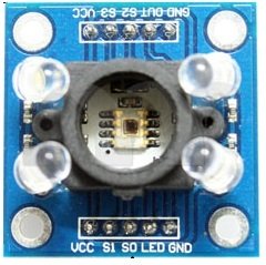
The sensor has 10 pins.
The pins of this chip are summarized in the table below.
Since 2 of the pins are redundant, VCC and GND, the table shows a description of 8 pins.
| TCS3200 Color Sensor | |
| Pins | Function |
| VCC | This is where you feed the positive voltage to power the chip. |
| GND | This is where you connect ground to in order to complete the electrical pathway. |
| S0 | With S1, these determine the scaling of the output frequency. |
| S1 | With S0, these determine the scaling of the output frequency. |
| S2 | With S3, these pins determine the color sensed by the sensor. |
| S3 | With S2, these pins determine the color sensed by the sensor. |
| Output | The Output pin gives the output frequency (of the color sensed) |
| LED | If connected to 5V or to a digital pin, the LEDs on the chip board will light up. |
So now you know the functions that each pin has. But to go a little more in depth, we give a few tables below on how exactly pins S0-S3 work.
Probably, the most important of the 2 pins are S2 and S3. These determine the color that has been sensed. Since these are 2 pins (S2 and S3) and each one can be HIGH or LOW, there is a total of 4 combinations possible.
The table below shows the combinations and the output resultant from these combinations.
| S2 | S3 | Photodiode Type |
| L | L | Red |
| L | H | Blue |
| H | L | Clear (no filter) |
| H | H | Green |
How the sensor works that it has color filters. When you choose a color filter, it can only allow one particular color to get through and prevents the others from getting through. Selecting the different variety of combinations for S2 and S3 picks certain filters. So if you select S1 as LOW and S2 as LOW, for instance, this makes a red color filter, where only red color can go through. So if the color goes through, then the sensor knows that red color has in fact been detected. So if no color goes through and these filters are applied, then that means that the color is not red. And this is how it works for all the other colors.
S0 and S1 are much less important for our purposes. But they can be useful for more advanced uses.
This is summarized in the table below.
| S0 | S1 | Output frequency Scaling (f0) |
| L | L | Power down |
| L | H | 2% |
| H | L | 20% |
| H | H | 100% |
Powering down the sensor is a power saving method. It holds the output at a high-impedance state. It’s similar to the output enable pin. But powering down the sensor with this pin saves much more power than disabling the sensor with the output enable pin. So it’s much power efficient. To do this, you would just make S0 and S1 both LOW.
The other combinations change the scaling of the output frequency.Scaling is accomplished by connecting the output signal of the converter to a series of frequency dividers. All divided outputs have a 50% duty cycles but we can change the frequency of the signals by either 100%, 20%, and 2%.
The frequency-scaling function is useful for optimizing the frequency output obtained from the TCS3200 sensor with other devices. The scaled-down outputs may be used where only a slower frequency counter is available, an example being a low-cost microcontroller, or where period measurement techniques are used. Again, this is for more advanced applications.
Color Sensor Circuit
The color sensor circuit we will build is shown below.
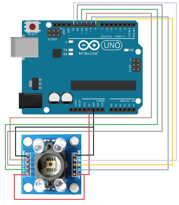
This color sensor circuit has quite a few connections.
First we connect power. VCC connects to 5V on the arduino board and GND connects to GND on the arduino. This establishes power to the TCS3200 chip.
For more detail: How to Build a Color Sensor Circuit