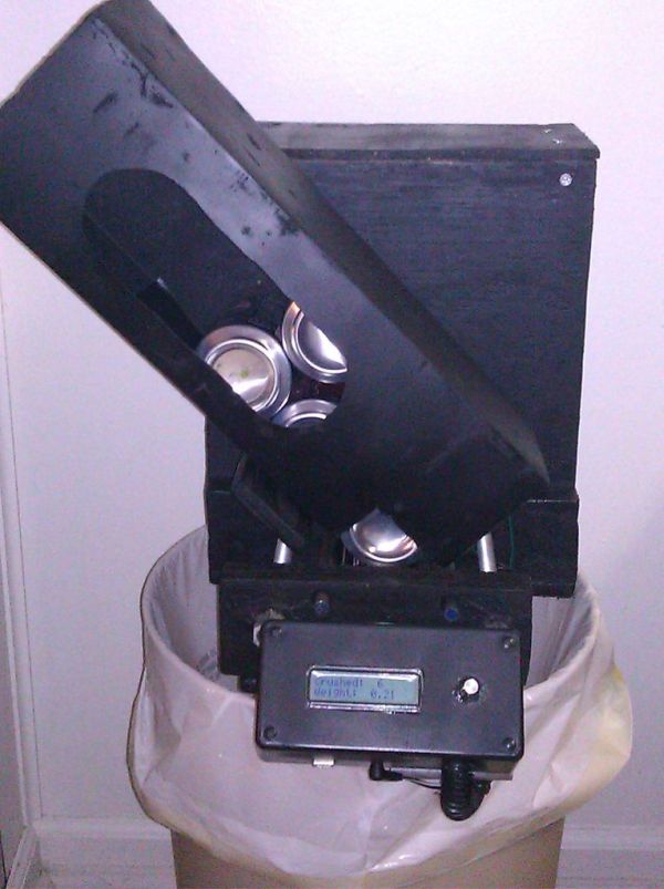
I have always wanted to do an instructable, but I never had a somewhat original idea that hasn’t been done a million times, or something that had no means of building. I have some friends who recycle aluminum for money and after seeing the large bags of an unknown amount and weight of uncrushed cans, I decided to make a machine that would crush the cans, count the cans, and tell the weight of the number of cans that it has crushed. I searched the internet and have found no machines that count the cans that have been crushed or tells the weight of the total crushed weight and could also be made from low cost and recycled materials.
Once I knew that this was a one of a kind idea, I drew up a rough plan on google sketchup to act as a starting schematic. I wanted to build the main chasis out of wood using mostly handtools so anyone could build one without a wood shop. The actuator (the crushing part) is driven by a old windshield wiper motor that my dad had laying arround, attached to two threaded rods by a belt and pulley system. There was an arduino that was sitting arround the house doing nothing, so there was no question that that would be the brains.
Step 1: Tools and Parts
Minimum tools required:
Safty goggles
Hearing protection
Hand saw
Drill
Drill bits- 5/8, 1/2, 1/4, 1/8
Cross tip bit or screwdriver.
Hammer
Exacto knive
Vicegrips or adjustable wrench
Soldering Iron
Ruler
Pencil or pen
Materials required:
Plywood
1″x4″ board
(2ea) 1ft, 1/2″ threaded rods
(2ea) 1/2″ couplers (remember to make sure the threading is the same as the rods)
(1ea) 3ft 1/4″ smooth rod
(2ea) 1/2″ID 1-1/2″ OD pulleys
(25ea) #8 x 1-1/4″ Screws
(1ea) 1ft 1/4″ threaded rod
(4ea) 1/4″ nuts
(2ea) 1/4″ ID large OD washers
(2ea) 1/4″ lockwashers
(2ea) 1/2″ OD washers (ID same as the motor shaft)
1/2″ belt (diameter about 20″)
Fence pole mount
Plastic clothesline puley
Soda can box
Epoxy
Arduino
Large 12v motor (power window motor or windshield wiper motor)
Solder
Wire
1602 LCD screen
Project box
1/2″ Cable wrap
(2ea) Zipties
(3ea) Limit switches (SPDT submini lever switch)
Protoboard
Motor controller
Pins
Optional materials:
Sandpaper
Spray paint
Step 2: Part 1: Making the puley and mounting it on the motor.
The first step is to remove the pulley from the plastic holder on the laundry line pulley; to do this you have to cut the pin holding the pulley. A hacksaw should work but I used a dremmel to cut off the head. Once the pulley is free, use a 1/2″ drill bit to create a space for a washer to fit into the puley while leaving enough material to still have strength. Clip off the extra material and sand it down. Mount the pulley on the motor and place the fence pole mount on the base of the motor.
The motor may have three wires, one is connected to the a switch that changes the direction once the motor rotates so far, you don’t want to use that wire to power it. Use one wire from the motor and another connecting the lead to the base of the motor–it should spin continuously (use a bolt on the motor to attach the ground).
Step 3: Part 2: Building the chasis
The chasis is the “frame” that everything is connected to and operates.
First you will want to make the crusher, this is done by cutting two short section of a 1″x5″ (about 12″ each) cutting the 3′ smooth rod into 4 equal length pieces. I used junk pieces of wood I found. I used the diameter of a aluminum can to make the square in the middle. The square gives you the width of the final part as well as the the distance between the 4 1/4″ smooth rods. Towards the outercenter of the boards the actuators will be mounted. I placed the one of the boards on the other to make the holes in line. Drill out the outer holes (actuator mounting holes) to 5/8″ in one board and 1/2″. Next, place a 1/2″ coupler in the 5/8″ from the back, and add some epoxy. The inner four holes should be 1/4″ for the rods to be mount into on the board with 1/2″ holes on the outside (the other should be slightly larger), this will act as a can retainer/guide. The top and bottom portions of the boards should be trimmed to the diameter of a can.
After the epoxy dries you can now run the 1/2″ threaded rods through the boards and install the pulleys on the rods. Now place the belt on the pulleys along with the motor, then measure the distance from the bottom of the board to the top of the pulley, on the motor add about an inch and you have the height of the next board you need to cut for the front wall of the “box” the width is 12″. Remove the pulleys from the rods and place the board with the 1/2″ holes (the can retainer mount [not the one with the couplers in it]) and use it as a template to make holes in the front wall. Drill it out to 1/2″ using the can retainer mount board as a retainer, remove the template then drill the holes to 5/8″ so that the sleeves fit in them. Use some epoxy on the sleeves to keep them in the board. This should be flat on the side that meets the can retainer mount and should stick out on the other side (this will work to reduce friction). You can use this board’s width and height for the back wall of the box.
Align the front wall holes with the holes in the can retainer mount, drill 4 well placed 1/8″ holes through the back of the front wall into the can retainer mount and then screw them together using the 1/8″ pilot holes. Now install the threaded rods with the pulleys, place this on a piece of plywood, then mount the motor and belt, measure the distance from the front of the can retainer mount to the back of where the motor is plus the thickness of the back wall of the box. This will be used to draw an outline of the back part and to make a bottom for box. The outline should be drawn including the front part of the machine as well. This should look similar to the bottom on image 11 and 12. Now cut a square hole wider than the diameter of a can and length slightly smaller than the diameter of the can.
Add some supports fot the back and side walls to the bottom as shown in image 14. Now place the motor with the pulley on the belt, pull the belt tight and mark the top of the front board. Measure the distance and now make a 1/4″ hole in the back wall so the fence pole connector around the motor will hold the pulley up to the measurement on the back board that was taken from the front board. Use the 1/4″ threaded rod, lock washers, large OD washers, and nuts to mount the motor to the back wall. Measure the distance from the front and back wall and make top supports, side walls and top. Also be sure to drill a 1/2″ hole in the bottom for the wires.
Step 4: Part 3: Programing and circuit design
The Program :
#include <LiquidCrystal.h>
LiquidCrystal lcd(12, 11, 10, 5, 4, 3, 2); // LCD on pins 12, 11, 10, 5, 4, 3, 2.
int StartPin = 9; // switch input
int motor1Pin = 7; // H-bridge leg 1 (pin 2, 1A)
int motor2Pin = 6; // H-bridge leg 2 (pin 7, 2A)
int enablePin = 8; // H-bridge enable pin
int DirPin = 13; // Motor direction select
int DirSwCounter = 0;
int LastDirState = 15;
int Dir = 14;
int cansCrushed; // Initial number of cans crushed set to 0
void setup()
{
// INITIALIZE
pinMode(StartPin, INPUT);
pinMode(DirPin, INPUT);
pinMode(motor1Pin, OUTPUT);
pinMode(motor2Pin, OUTPUT);
pinMode(enablePin, OUTPUT);
digitalWrite(enablePin, LOW);
lcd.begin(16, 2);
lcd.print(“Can Crusher MKII”);
delay(3000);
lcd.clear();
lcd.setCursor(0, 0);
lcd.print(“Crushed:”);
lcd.setCursor(10, 0);
lcd.print((int)cansCrushed);
lcd.setCursor(0, 1);
lcd.print(“Weight:”);
lcd.setCursor(9, 1);
lcd.print((int)cansCrushed*.034375);
pinMode(StartPin, INPUT);
pinMode(DirPin, INPUT);
pinMode(motor1Pin, OUTPUT);
pinMode(motor2Pin, OUTPUT);
pinMode(enablePin, OUTPUT);
digitalWrite(enablePin, LOW);
cansCrushed = 0;
}
void loop()
{
// READ PINS
int DirState = digitalRead(DirPin);
if (LastDirState == LOW && DirState == HIGH)
{
DirSwCounter++;
}
LastDirState = DirState;
// PROCESS
if (DirSwCounter % 2 == 0)
{
digitalWrite(Dir, LOW);
cansCrushed++;
} else {
digitalWrite(Dir, HIGH);
}
if (digitalRead(StartPin) == HIGH && digitalRead(Dir) == LOW)
{
digitalWrite(enablePin, HIGH);
digitalWrite(motor1Pin, HIGH);
digitalWrite(motor2Pin, LOW);
}
else if (digitalRead(StartPin) == HIGH && digitalRead(Dir) == HIGH)
{
digitalWrite(enablePin, HIGH);
digitalWrite(motor1Pin, LOW);
digitalWrite(motor2Pin, HIGH);
} else {
digitalWrite(enablePin, LOW);
}
}
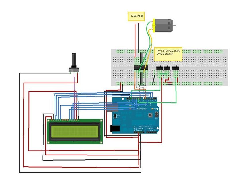
The wiring diagram for the machine is shown below.
For this design I used Fritzing, it is pretty awesome.
http://www.fritzing.org
Build the circuit board from this design, but don’t add the switches yet.
[box color=”#985D00″ bg=”#FFF8CB” font=”verdana” fontsize=”14 ” radius=”20 ” border=”#985D12″ float=”right” head=”Major Components in Project” headbg=”#FFEB70″ headcolor=”#985D00″]Soda can box
Epoxy
Arduino
Large 12v motor
Solder
Wire[/box]
For more detail: Arduino Controlled Can Crusher With LCD Readout