128X160 pixels in 18 bit color with a microSD breakout board courtesy of Adafruit Industries
You can purchase the 18-bit color TFT LCD display with microSD card breakout kit (part# ST7735R) from Adafruit Industries
This tutorial from Adafruit is for a 1.8″ diagonal TFT display & microSD breakout board. This breakout is the best way to add a small, colorful and bright display to any project. Since the display uses 4-wire SPI to communicate and has its own pixel-addressable frame buffer, it can be used with every kind of microcontroller. Even a very small one with low memory and few pins available!
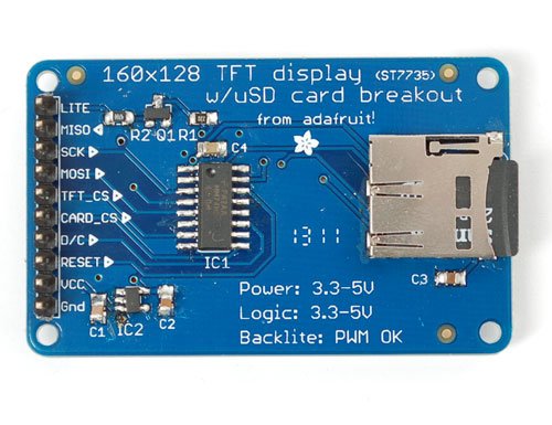 The 1.8″ display has 128×160 color pixels. Unlike the low cost “Nokia 6110” and similar LCD displays, which are CSTN type and thus have poor color and slow refresh, this display is a true TFT! The TFT driver (ST7735R) can display full 18-bit color (262,144 shades!). And the LCD will always come with the same driver chip so there’s no worries that your code will not work from one to the other.
The breakout has the TFT soldered on (it uses a delicate flex-circuit connector) as well as a ultra-low-dropout 3.3V regulator and a 3/5V level shifter so you can use it with 3.3V or 5V power and logic. Adafruit board also had a little space to placed a microSD card holder so you can easily load full color bitmaps from a FAT16/FAT32 formatted microSD card.
You can pick up one of these displays in the Adafruit shop!
Flexible wiring
There are two ways to wire up these displays – one is a more flexible method (you can use any pins on the Arduino) and the other is much faster (4-8x faster, but you are required to use the hardware SPI pins) We will begin by showing how to use the more flexible method.
You can use any 4 or 5 pins for this method. We’ll show using pins 4, 5, 6, 7, and 8 and once you have it working, you can change those pins around in the wiring and in the sketch.
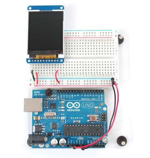
Start by wiring the power pins.
Connect the leftmost pin to Ground and the next pin to +5V. Connect the rightmost pin (backlight) to 5V as well. If you plug in the Arduino you should see the backlight turn on.
Next connect the RESET (TFT reset pin) and D/C (TFT data/command selection pin).
The RESET pin (3rd from the left) connects to Arduino pin 8. The D/C pin (4th from the left) connectso to pin 7
Finally connect the remaining digital pins, TFT_CS (TFT chip select), MOSI (data sent to TFT) and SCK (clock sent to TFT).
Note that you need to skip a pin on the TFT after D/C – the next wire is from TFT_CS which is 6th from the left. This goes to digital pin6. MOSI (7th from the left) connects to digital pin 5 and finally SCK (8th from the left) connects to digital pin 4
That’s it! If you want to change the wiring, you can use any pins but don’t forget to change the top of the sketch to match!
//You can use any (4 or) 5 pins #define sclk 4 #define mosi 5
#define cs 6 #define dc 7 #define rst 8
// you can also connect this to the Arduino reset
Test Display
Once you have the display wired up, its time to test your wiring by uploading the example code we have written. Adafruit suggest using an Arduino to test.
Download Adafruit’s Arduino library (see bottom of page) from github by clicking on Download in the top right corner. Uncompress the folder and rename it ST7735 – inside the folder you should see the st7735.cpp and st7735.h files. Install the ST7735 library foler by placing it in your arduinosketchfolder/libraries folder. You may have to create the libraries subfolder if this is your first library.You can read more about installing libraries in this tutorial
Restart the Arduino IDE. You should now be able to select File > Examples > ST7735 > graphicstest sketch. Upload the sketch to your Arduino wired as above.
Once uploaded, the Arduino should perform all the test display procedures! If you’re not seeing anything – first check if you have the backlight on, if the backlight is not lit something is wrong with the power/backlight wiring. If the backlight is lit but you see nothing on the display make sure you’re using our suggested wiring
 High Speed SPI-Wiring
If you want to connect to the display and have high-speed data transfer (4-8x faster) you’ll have to use the hardware SPI system. This is optimized to be faster than the flexible wiring method (because its built into the hardware of the chip) but you are required to use the hardware SPI pins!
On Atmega 328/168/8 type Arduinos (‘classic’ type) the hardware SPI pins are 11 (MOSI), 13 (SCK) and 10 (CS). For Megas it is 51(MOSI), 52 (SCK), and 53 (CS). The CS pin can be a different pin but if you use any other pin you must still have the hardware SPI CS pin (10 or 53) as an output!
We will also change the TFT_CS pin to be pin 10 and D/C to be pin 9 (you can change these two later but pin 10 must always be an output for hardware SPI to work)
For more detail: TFT Display with microSD breakout board