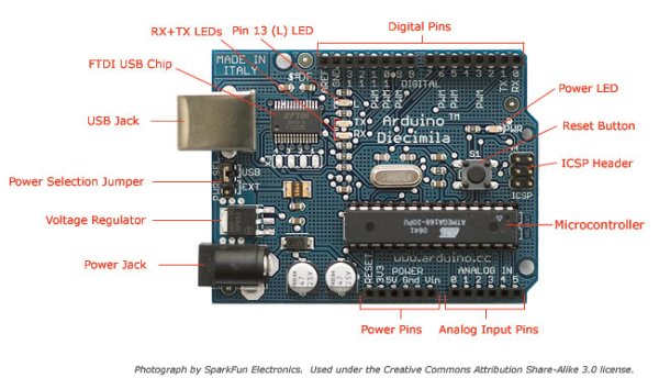
The Arduino offers the advantage that a lot of people are using it so it is usually quite easy to get help or information via the internet. The main website for the Arduino is: http://www.arduino.cc/. The Arduino can also be programmed to behave in many different ways. It has 6 analog pins (continuously varying controls like a light sensor) and 14 digital pins (on off switches for example. All of these pins can be either inputs or ouputs meaning that as well as transducing information from a sensor a pin could be used to, for example, turn on a light, activate a motor or solinoid. Its analog pins offer a high resolution (10 bit) which means 1024 different values which is superior to the 7 bit / 128 values of a MIDI continuous controller. A disadvantage of the Arduino is that communication with software is not as simple as with MIDI although if you are using software for which there are already implemented interpretters such as MaxMSP or PD then this won’t be a problem. If you need to convert the Arduino’s data to MIDI you could try Junxion. If you just want to use the Arduino as a sensor interface you will need to program it with a so-called Firmata. This is a simple procedure which is carried out from the Arduino environment program, downloadable from the Arduino website.
Another option we looked at for the input of analog / continuous sensors was the Doepfer Pocket Electronic The Pocket Electronic has 16 analog inputs and outputs data as MIDI continuous control messages so it is easy to interface with a wide variety of software and hardware.
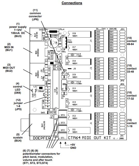
The Doepfer CTM64 offers 64 digital inputs (on/off switches) and outputs each switch as either a MIDI note on/off message of as a MIDI continuous control message (on=127,off=0).
An obvious implementation would be to connect the switch inputs to the keys of a keyboard but any number of more imaginative implementations are possible.
2. Sensors
A linear potentiometer with a value of 10 kilo-ohm is normally a good choice with sensor boards although as this is a potentiometer (3 connections) and not a variable resistor (2 connections) the precise value value shouldn’t matter too much. If you were to use an extremely high value pot, say 10 megaohms then the sensor input might struggle to hold a stable value. If you used an extremely low value, say 10 ohms then it may not be able to reach to minumum and maximum values for the sensor input.
No additional resisitor is required this time as there is always some sort of connection to ‘ground’ within the potentiometer. If the control is turned fully counter-clockwise then there will be close to zero resistance between the input and ground (GND.) and maximum resistance (e.g. 10k) between input and +5v. The input will receive 0v and the sensor will give a minimum value, zero for MIDI. If the control is turned fully clockwise then there will be maximum resistance between input and ground and minimum resistance between input and +5v, the input will receive 5v and therefore a maximum sensor reading which in the case of MIDI will be 127. If the control is exactly in the middle then there will be equal resistance between input and ground and between input and +5v. If we are using a 10k linear potentiometer then this resistance will be equally divided, there will be 5k between input and ground and 5k between input and 5v.
Experiment with different types. Larger ones (with more wavey lines on them) will tend to provide a lower minimum resistance and therefore output a wider range of values. You can expect to pay the equivalent of 1 euro or more for a decent one.
Connecting two or more smaller LDRs can provide equivalent behaviour to a single larger one.
As this is a varible resistor (2 connections) as opposed to a potentiometer (3 connections) we need to connect a 10k static resistor between the input and 5v. You can experiment with different values for this static resistor, perhaps within the range 5 – 100k. Depending on the LDR you are using you will get a different range of output values but the scope of the range will probably not change. It is unlikely that an LDR will yield a full range of sensor values but obviously better lighting conditions will increase the range possible.