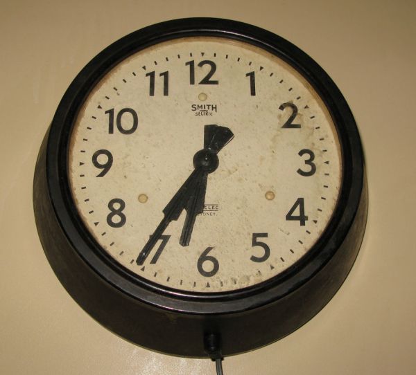
One day while exploring the bric-a-brac at the markets, I stumbled across an old, Bakelite slave dial from the 1950’s.
Slave Dials are clock movements without the actual time keeping circuit. All they contain is the mechanism to drive the hour and minute hands, which can be advanced by an electric pulse. This pulse is sent by a centralised master time-keeping mechanism. They were often used railway stations or large office building to ensure that all the clocks read the same time. You will still occasionally find such dials at markets, car-boot-sales and disposals.
I like the idea of bringing new life to old technology, and so conceived of the idea of melding the slave dial with a micro-controller and internet connection to create a old style slave dial with atomic clock accuracy.
These steps describe the process I went through, and includes all the schematics and source code. This same technique might also be applied to modern clock movements by bypassing the existing pulse-generation circuit.
Materials
- Arduino with WiFi (I used a YellowJacket board from Async Labs, but you could use any Arduino with WiFi or Ethernet enabled or a suitable shield).
- Stripboard.
- LM317 Regulator.
- TIP31 Transistor.
- 1N4004 Diode.
- Red LED.
- 9V Power Supply.
- DC Power Socket (to suit power supply).
- 0.1uF Capacitor.
- 1uF Electrolytic Capacitor.
- 22R Resistor.
- 3 x 1K Resistor.
- 10K Resistor.
- 100R Resistor.
- Self-adhesive Velcro.
- Electrical Tape.
- Foam (for sound insulation).
Step 1: Identify Slave Dial Characteristics
When I purchased the salve dial, it came with no instructions, packaging or other details. The only markings (other than five decades of grime) were those on the face (SMITH SECTRIC, ACELEC SYDNEY), and some markings on bracket holding the mechanism together (E.C.S. 205/19 MADE IN ENGLAND)). There were markings on the coil, but they were too faint to read.
In order to drive the mechanism, I needed to know how much voltage had to be applied to the coil to reliably advance the hands, for how long, and how many seconds the hands would advance for each pulse. I was concerned about overdriving (and hence damaging) the coil, but also concerned about under-driving it, resulting in an unreliable movement.
I was able to find some general information on these units on the web (thanks to Google). My thanks to the people who put together the English Clock Systems website. It turns out that most such clocks would advance either 30 or 60 seconds depending on the model. The mechanism was specified as a combined resistance of around 3.5 ohms, and a current rating of 0.3 amps, for an operating voltage of 1.05 volts. IN reality, most such units were driven by banks of old dry-cell batteries with a voltage of 1.5 volts, so that is what I aimed for.
Note that slave dials such as this typically had a “shunt” resister is parallel with the coil. The reason for this was so because these clocks were often wired in series. Without the resister, if the coil on one clock went open circuit, all the clocks would stop working.
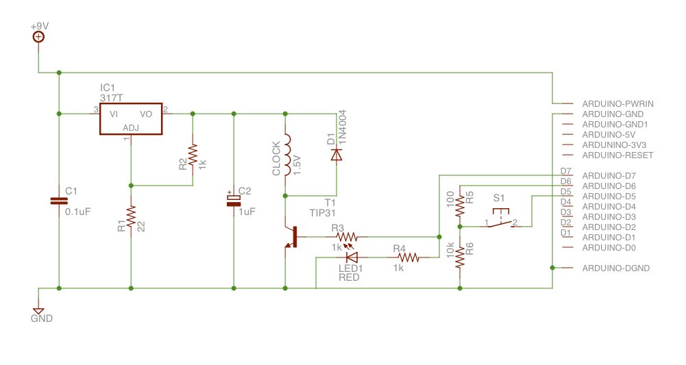
Step 2: Design Drive Circuit
The circuit needs to be able to drive the clock’s coil at 1.5 volts are there-abouts. I’m sure there are more elegant solutions, but I simply used a variable regulator (an LM317) to supply the voltage, and a the output from this is switched via a transistor (TIP31). Note that due to the voltage drop across the transistor, the regulator actually has to supply around 3V. A diode is place across the clock coil to reduce back-EMF.
The switching transistor is driven via one of the Arduino’s output pins. I put an LED in parallel to help with debugging (so I can test the program without having the clock wired up). Finally I wired up a switch to one of the Arduino’s other pins. The intent was to use this to enter a configuration mode (e.g. to setup the wireless network settings) however I never actually made use of this.
The Arduino I chose is a YellowJacket from Async Labs. Unfortunately they are no longer making them. If you check their forums (which will remain up for a while), you may find people putting together their own runs (open source hardware never dies after all). Alternatively, a different Arduino could be used. For example, a standard Arduino with an Ethernet shield could be used (with some code changes to accommodate the different network libraries). In this case, using POE (Power Over Ethernet) would also eliminate the need for a separate power cable. Rather than using a network time source, a GPS unit connected to a standard Arduino could also be used.
I used the freeware version of Eagle to document the circuit, prototyping each segment as I went.
With the circuit design and prototyped on breadboard, I moved to building it on some stripboard. I use a little Java application called DIYLC to design the strip-board layout.
Step 3: Build and Install Circuit
Assembly was fairly straightforward. I cut a piece of strip-board to size, then cut the tracks at the designated points using a drill bit. Note that I used
After that its just a case of cutting a piece to size, breaking the tracks at the appropriate points with a drill bit, and soldering everything together. Note that I used a set of single inline header sockets and pin headers to mount the Arduino. This allows me to remove it if needed. I also fitted a DC power socket to suit my power supply.
The PCB was mounted inside the clock using double-sided Velcro. I used some electrical tape to insulate it from the metal back-plane of the clock. The power socket was glued in place using some two-part epoxy. I did have to clean the area a bit first and use a little sandpaper on both the clock and the socket in order to ensure a good bond.
[box color=”#985D00″ bg=”#FFF8CB” font=”verdana” fontsize=”14 ” radius=”20 ” border=”#985D12″ float=”right” head=”Major Components in Project” headbg=”#FFEB70″ headcolor=”#985D00″]
- Arduino with WiFi
- Stripboard
- LM317 Regulator
- TIP31 Transistor
[/box]
For more detail: Make an Atom Synchronised Clock from a 1950’s Slave Dial using Arduino