I design and create this Palm Arduino V3 prototype PCB, as I was tired of recreating Arduino Compatible on perf board every time I prototyping a new project, especially when I had to spend a lot of time tracing the wiring to see that I made the right connection.
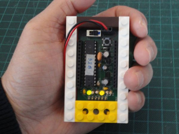
I design this Palm Arduino (version 3) prototype PCB to be encased by Lego bricks, especially Lego Technic Bricks, for the reason that I was hooked by the Lego after my first Lego project – R/ C Lego Car. And I am working on a couple projects that are using Lego Technic components with Arduino. (I will post instructables as the project is ready to post.)
Also, I want to be able to use Palm Arduino in wide variety fashions. For example I could use either right angle female connectors or straight female connectors. or could use straight power switch or right angle power switch. etc. By doing this, I would facing the challenge of the enclosure designs to fit all of the mentioned criterial, and not very cost effective since we have to make 3D Print for each individual case.
For these reason Lego bricks are the best option to be used as the case of Palm Arduino Version 3.
Step 1: Schematics and Pin Configurations
Palm Arduino and Palm Arduino II
Original Palm Arduino and Palm Arduino II, have a straight forward pin configurations. The order of the pin configuration were the same as the order of the pins of ATmega328 micro controller (28 pins)
1 – RESET 28 – A5 (SCL)
2 – D0 (RX) 27 – A4 (SDA)
3 – D1 (TX) 26 – A3
4 – D2 25 – A2
5 – D3 24 – A1
6 – D4 23 – A0
7 – VCC 22 – GND
8 – GND 21 – AREF
9 – XTAL1 20 – AVCC
10 – XTAL2 19 – D13 (SCK)
11- D5 18 – D12 (MOSI)
12 – D6 17 – D11 (MISO)
13 – D7 16 – D10 (SS)
14 – D8 15 – D9
Both Palm Arduino and Palm Arduino II requires an addition of power regulator (5V and 3.3V).
Palm Arduino Version 3
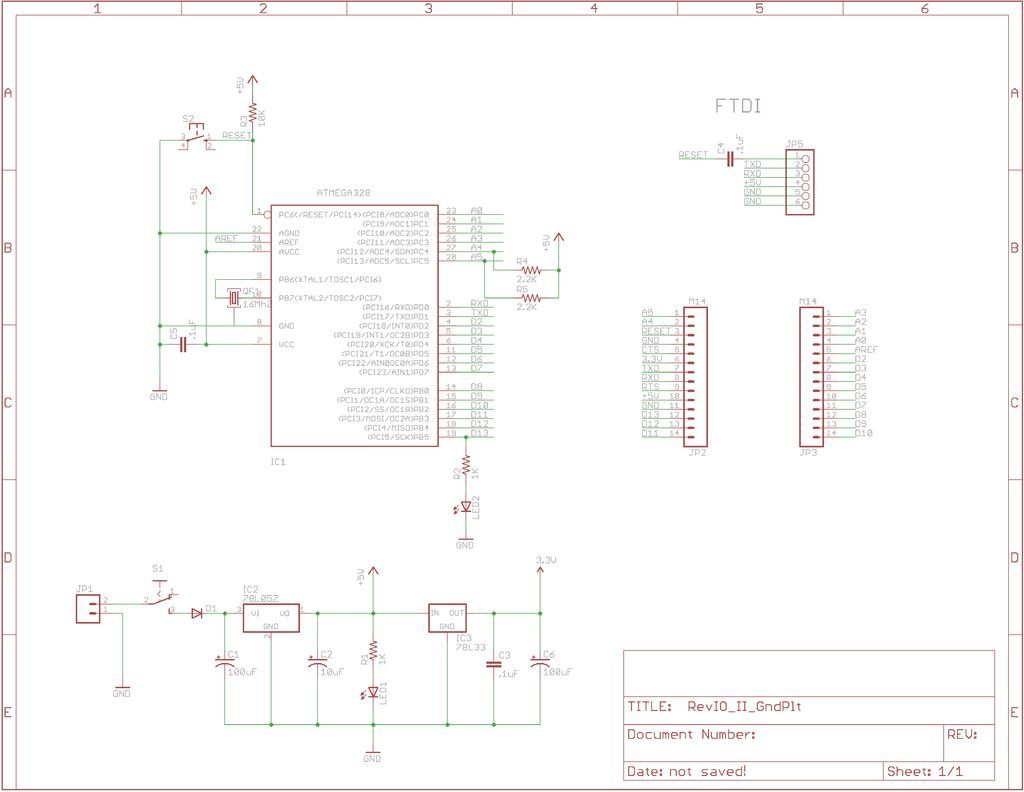
In Palm Arduino Version 3, I used the same pin configuration that I designed for my other Arduino compatible board, RevIO, by grouping the communication ports (I2C, Serial Comm. Ports and SPI) on one side of the board, and leave the rest of the pins (Digitals, and Analogs) line up on the other side of the board sequentially (image 1).
I also group the serial comm. pins (TX, RX, VCC, GND) on the rail to to be compatible with the XBee breakout board, such as XB-Buddy Basic Kit, Adafruit’s XBee Adapter Board (ID-126), or Sparkfun’s Bluetooth Mate Gold (WRL-09358), etc.
Palm Arduino V3, added voltage regulators (5V and 3.3V) circuitry onto the PCB.
I designed the Palm Arduino Version 3 to have its dimension compatible with the Lego’s modular system.
Instead of using an ordinary standoff holes on four corner of the PCB, I added four larger holes that can accommodate the Lego’s stud, so the PCB could hold on to the Lego’s bricks or plates.
Step 2: Design Processes
PCB and Case Design
Lego Modular System has been in my interest long before I created my first Lego project, R/C Lego Car. I have been researching on Lego bricks and components for a while, I also build my own Virtual Lego Bricks and Plates, and components according to the real dimensions, now I have good amount of components in my Lego Bricks and Plates library.
Since I planned to build Palm Arduino V3, I could use the Virtual Lego Bricks and Plates from my library to good use.
First, I design (virtual) Palm Arduino PCB in EagleCAD, using exactly the same components as in my other Arduino compatible board, RevIO. The RevIO PCB is larger than Palm Arduino V3.
I planned the layout of Palm Arduino V3 to have the dimension fit with the Lego Modular System, and created the PCB in EagleCAD.
Then send the Gerber files to make the sample PCBs (I ordered four of them).
After I finished with the PCB layout I created Virtual PCB with CAD program (Autodesk’s 3DS Max 8). To make a complete virtual PCB, I also created all the (virtual) electronics components that were necessary in Palm Arduino exactly with the real dimensions. And placed them on the virtual PCB.
The silkscreen on the PCB came from the rendered image from PCB fabricator. I used the image as a texture map on the Virtual PCB.
To design the case, I imported the necessary Lego Bricks and Plates into the virtual PCB and design the variations of the components configurations and different case styles, as presented in the following Steps..
[box color=”#985D00″ bg=”#FFF8CB” font=”verdana” fontsize=”14 ” radius=”20 ” border=”#985D12″ float=”right” head=”Major Components in Project” headbg=”#FFEB70″ headcolor=”#985D00″]78L052
ATMEGA328[/box]
For more detail: Palm Arduino Board V3