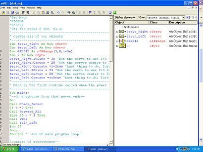
I created this Instructable for the absolute n00by robot wannabe. I have noticed a huge jump in the number of beginners getting into the hobby and the number of “how do I” questions seem to be mounting. Maybe this humble little Instructable will help one or two create their first robot. You will find basic source code at the end of this Instructable.
Don’t panic at the number of steps… I broke the robot down into many tiny little steps for ease of following.

This little robot is nothing more than a simple plywood platform that carries a couple of modified model airplane servos as the main drive system, a microcontroller and a IR sensor. I designed in plenty of room to expand and add on. You should be able to build it in about 3 hours if you have the parts on hand.
The microcontroller I chose is the OOPic R. I picked this micro because the dozens of built in objects and sample codes make it easy for the beginner to get up and running quickly. They can be found from any of the major robot parts suppliers for usually less than 60 bucks. Get the starter kit as it has a programming cable and battery clip included.
You can use any microcontroller as long as you can plug a servo directly into it (that shortens the list, lol).
The servos listed are all Hitec HS-311 model airplane servos found at nearly any hobby shop for less than 10 bucks in some cases.
The IR sensor is a Sharp GP2D12 Analog unit available from Digikey (www.digikey.com). Any of the GP2D12XXX analog series will do the job.
The Tailwheel is a simple Dubro .20-.40 model airplane 1″ wheel with mount. Pick one up at the hobby shop where you get your servos.
The wood base is a scrap piece of 1/4 inch birch plywood and the servo / sensor mount is a scrap piece of just about anything wooden. I used a piece of fir.
I made the billet aluminum wheels myself but you can use any wheel designed for servo attachment.
The rest of the robot consists of a few screws and some electrical standoffs.
Without the SPECAIL add on at the end it cost me about $95.00 USD. The special step adds about 50 bucks.
Be nice as it is my first Instructable.
Step 1: Tools and Materials
Parts list:
-ooPic R Microcontroller (http://www.thebotshop.com/)
(note – You can use whichever microcontroller you are comfortable with)
-Sharp GP2D12 With wired JST connector
-Billet Aluminum Wheels/Tires (or equivelent)
-Hitec HS-311 Servos, Modified
-Super Glue
-.5 X 1 inch Double Sided Tape
-1/4 inch Plywood and a piece of scrap wood
-Dubro .20-.40 RC Airplane Tailwheel assmbly
-Misc. spaces/standoffs and screws/nuts-9 Volt battery
-Heat shrink tubing 1/16 x 3 inches
-3 standard female crimp pins (do not panic if you cant get them)
-Paint *optional
-9 volt battery
Tools:
-Misc Small Screwdrivers
-Needle Nose Pliers
-Drill and bits
-Saw
-Soldering Iron
-Solder
-Sandpaper
-Sharp Pencil
-Ruler
Total Cost approx. $95.00 USD
Time to Build approx. 2.5 – 3 hours
Step 2: Modify the servos
You will need to modify your servos using the super glue the potentiometer method. I chose not to waste space by detailing it here as there are dozens of articles on Instructables and Google showing you how. If demand calls for it I will add it here later.
Essentially you need to tear them apart, find the 90 (no movement) position, super glue the pot top and bottom, put it all back together, modify the output gear, file off the top of the pot shaft flush with the case mold.
The Hitec HS-311 has a plastic pot shaft that makes it easy to file down. If you use a different servo that has a metal pot you must alter the underside of the output gear instead.
Potentiometer = Pot = Variable Resistor
Step 3: Cut the wood parts
Cut a piece of 1/4 inch birch plywood or equivelent, into a 3.25 inch square for the base.
**SPECIAL**
Cut a second piece of 1/4 plywood matching the first for a easy add on later.
Cut a piece of scrap wood into a 2 5/16 inch long, 3/4 inch tall, 1/2 inch thick GP2D12 mount.
The scrap servo / IR mount could be made by laminating 2 pieces of the 1/4 inch birch plywood together.
When everything is cut out give it a gentle sanding to clean up any rough or fuzzy edges.
Step 4: Drill the holes
Using your microcontroller as a guide, layout the mounting holes on the plywood favoring the front as shown.
Using the tailwheel mount as a guide, layout the mounting holes on the plywood favoring the rear as shown.
Drill all holes with a 1/8 inch drill bit.
If you chose to make the spare base piece from **SPECIAL** in step 3, then clamp the two bases together and drill the microcontroller holes at the same time. Seperate the two pieces and drill the tail wheels holes in one of them only.
Step 5: Install the servo / IR mount
Super glue the servo / IR mount from Step 2 to the bottom of the plywood making sure to center it left and right as well as flush it up with the front edge of the plywood as shown.
Step 6: Drill holes for servo wires
Temporarily places your servos in their mounting position behind the servo / IR mount and you will notice that the wires hit the mount on the back side. We will need some holes to allow the wires to pass through. Servos must be oriented so that the output shafts are closer to the front of the base, not the rear.
Using a servo as a guide, determine and mark where the holes need to be drilled on the mount.
Using your pencil and ruler, transfer those points to the front of the mount as shown in step 4.
Drill holes with a 5/16 drill bit. Be careful, you can split the wood. Never fear, if you do just super glue it together.
OPTIONALLY you can reroute the servo wires through a small hole drilled in the bottom of the servo during modification and avoid this step alltogether.
Step 7: Tailwheel
Install the tailwheel assembly at the center rear of the base as shown using a couple of 4-40 X 1/2 inch machine screws and nuts.
Make sure the screw heads, or nuts depending on orientation, get countersunk into the plywood so they do not interfere with servo installation.
Do not worry about height right now, we will adjust it later.
Step 8: Install standoffs
It is best to get your board standoffs mounted right now before the servo go in.
Using a 4-40 X 1 inch screw, a 4-40 x 1/4 inch standoff and a 4-40 nut, install one in each microcontroller hole as shown.
Make sure the screw heads get countersunk into the plywood so they do not interfere with servo installation.
For more detail: Super Simple Beginners Robot!