This summer, my hackerspace LVL1 (in Louisville, Ky) got an awesome laser cutter http://fslaser.com/40w-deluxe-hobby-laser-engraver-and-cutter. LVL1 is an awesome community of creative folks that like to build stuff. You can always check out what we are up to at http://www.lvl1.org. If you like instructables and making stuff, you should see if there is a hackerspace in your area. Anyway…
I decided to build a gear clock after seeing something like what I made in a friends office and after playing with the gear renderer in Inkscape. This instructable hopefully will show you how to make what I made and also teach you a little about the design process involved when working with a laser cutter.
Step 1: Gather your materials.
For this instructable I needed…
- 2 small stepper motors. I used Symbol 21-02485-03 steppers that I bought from electronics goldmine. Unfortunately they no longer sell them. http://www.goldmine-elec-products.com/prodinfo.asp?number=G14197 I will keep looking for another source.
- 1 Arduino (actually, I used a Freeduino – http://store.nkcelectronics.com/freeduino-arduino-diecimila-compatible-board-complete-kit.html)
- 1/8″ birch plywood (You can buy this at Michaels or Hobby Lobby) it cuts really nicely.
- Inkscape (http://www.inkscape.org)
- Laser Cutter
- Optional Chronodot from Macetech (http://macetech.com/store/index.php?main_page=product_info&cPath=5&products_id=8&zenid=f63efb4e6b02850ef3da2f48cf86d70e)
You will also need a computer to program your Arduino and also for designing in Inkscape.
Step 2: 1st prototype
For the first prototype, I just wanted to see if I could get the stepper gear thing working at all. I cut a spur gear for the stepper, a small stand with a hole in it to press fit the stepper motor and a larger gear that would be the clock mechanism.
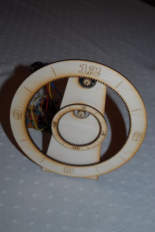
After assembly and a quick program, I decided that the clock needed to have two gears (and thus two stepper motors) – one for hours and one for minutes. I also discovered that the numbers needed to always be right side up as the gear traveled around. Thus, the 6 needed to be upside down in the drawing as well as the 3 and nine needed to face outwards.
Another cool thing I discovered during my first prototype is that the Arduino has enough power to step these motors without having a driver circuit. This makes the clock considerably easier to make! Here are a couple of links to tell you about how to hook up the Arduino to the stepper I used…
http://ryanschenk.com/2010/03/driving-a-040-stepper-with-arduino/
http://profmason.com/?p=173
I also began to think about my gears. In my prototype, I used a 10 tooth gear for the gear connected to the stepper and a 100 tooth gear for the ring. 100 really does not translate well into hours or seconds so what else could I use?
My stepper gear has 10 teeth and this actually works well because the stepper I am using has 20 steps per revolution. Thus I can step the stepper 2 times to move exactly 1 tooth.
Therefore, for my minute hand, if I use 60 teeth, then each 2 steps = 1 minute = 1 tooth of movement.
Similarly, my hour hand has 144 teeth because if we divide it by 12, each hour has 12 teeth and therefore each tooth is equal to 5 minutes! Really, the clock does not have to have a minute ring at all. The hour ring can tell you what time it is.
Step 3: Using Inkscape to draw gears.
Start by opening Inkscape and creating a new document. I like to use letter landscape as the document size. That size fits in our laser cutter well. File->New->Letter_landscape
From there I find it helpful to turn on a grid. File->Document Properties Grids tab. Set your grid to what you feel comfortable using, I like to work in inches, but others work in mm’s. It really does not matter.
Now the fun part… To put a gear on your drawing, use Extensions->Render->Gear. When I did this clock I used a circular pitch of 10 and a pressure angle of 10. Then I varied the number of teeth to set the gear size. As long as I used 10 and 10 for circular pitch and pressure angle, the gears fit! Please go ahead and try it!
Once you have drawn a gear, you will most likely need a center hole. To get a hole centered on a gear, draw the gear and draw the circle for the hole. Then select both the circle for the hole and the gear and go to Object->Align and distribute. Then click the icons that say ‘Center on the Horizontal Axis’ and ‘Center Horizontally’.
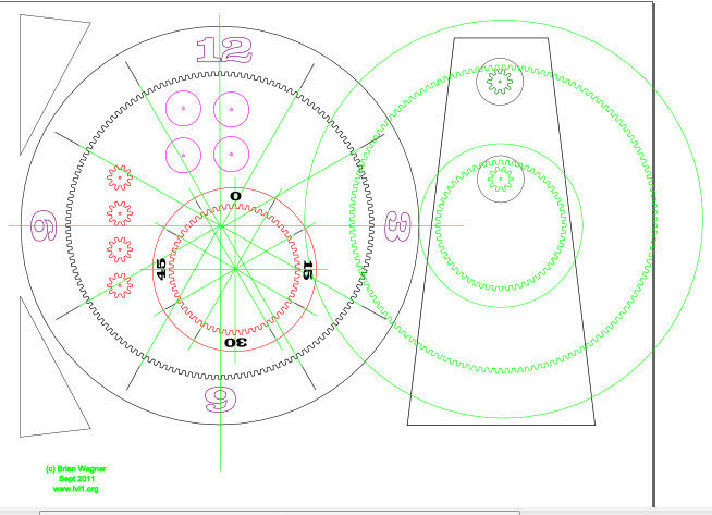
I have attached my file for cutting the gears. It is called ClockGear3.svg and you can download it below. The green lines in the file are lines that I use for guides. I do not cut anything in green.
The stand is the tall trapazoid and the two triangles. I hot-melt glued the triangles to the back of the stand.
*** UPDATE 2/29/12 ***
If you try to download the inkscape file, it will download as something.tmp. Just rename it to clock.svg and then you can open it in inkscape.
 GearClock3.svg79 KB
Laser Cutter[/box]