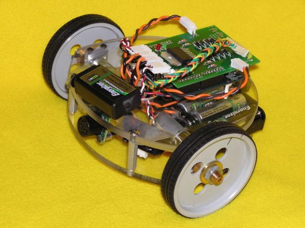
Objective: To create from scratch a working robot that is able to avoid walls and obstacles.
Ever wanted to make a robot that could actually do something, but never had the time or knowledge to do it? Fear no more, this instructable is just for you! I will show you step by step how to make all the necessary parts, and programs to get your very own robot up and running. I was first inspired to build a robot when I was ten, and saw Lost in Space, with that famous B-9 robot, I wanted one! Well six years later I finally built a working robot, its name- Walbot of course!
Step 1: Gathering supplies
Now is a good time to order and collect some of the things you will need for this project. The “brain” of Walbot is a Microcontroller by Atmel called the Atmega168, it is very fast, easy to use and cheap, so that is what I will be using in this project. If you prefer to use PIC, or other Microcontrollers thats fine, however I can’t help you out with the code then! Since I did not feel like wasting my time building a prototyping board for the Atmega168, I bought the USB Arduino; it is very easy to use, supports USB, has the boot-loader already burned in, quite cheap, and has free programming software that is similar to C++. Well enough of that talk, let’s get on with what you will need!
note: these are only the prices I found from a quick search, if you look harder you probably will find better prices somewhere else, also the DIgiKey links might be broken or timed out, just search for the part description and whatever price matches the one listed here.
Parts:
Arduino USB board – $34.95
LV-EZ1 Ultrasonic Rangefinder– $25.95
2X 54:1 16mm Spur Gearmotor, FF-050– $13.80
2XPack of 4 Energizer NiMH AA Batteries– $4.85
9Volt Energizer NiMH Battery– $8.99
2X3mm Aluminum Bearing Block– $3.50
2X 3xAA battery holder (DigiKey part # SBH-331AS-ND – $0.98
2.1 x 5.5 x 9mm Right angle DC Power Plug – $0.95
2X Noise Suppression Capacitors – $0.50
L298 double full H-Bridge – FREE SAMPLE!
12″X12″ sheet of 1/4″ Lexan polycarbonate – $16.36
3X Aluminum 1″ 8-32 standoffs – $0.45
4X 2-56 X 1/4 BUTTON CAP SCREW – $0.37
BOX of 100 4-40 X 3/8 BUTTON CAP SCREWS – $5.40
3X 8-32 X 3/8 BUTTON CAP SCREWS – $0.29
Neoprene Foam Tire – 3″D x 0.75″W (pair) – $5.36
Mounting Hub – 3mm (pair)– $8.00
9Volt battery clip (DigiKey part # 234K-ND)
Break Away Headers – $2.95
2 red 2 green and 1 yellow 3mm LED – $2.20 total
4X 1N5818 SCHOTTKY Diode (DigiKey part # 1N5818-E3/1GI-ND) – $0.15
2X 47k and 2X 2.2k and 1X 10k resistirs (digikey part #’s P47KBACT-ND and P2.2KBACT-ND and P10KBACT-ND) – $0.34
Ping Pong ball or other small low friction sphere for a caster- Free????
Custom order Arduino circuit shield see step 4
Optional / If your a complete beginner:
22AWG High Strand Count Silicone Wire Combo Pack – $16.80
Polarized Connectors to make things look neat, you will need crimp pins, 4X 2 pin header and housing, 4 pin header and housing – $6.45
Velcro for sticking things to base
Tools
these are the suggested tools to have for this project, you could either buy borrow or use something else you have for the same purpose.
Bandsaw for cutting the Lexan base and various parts.
Drill Press for drilling straight holes in Lexan base.
Tap and Die set for tapping holes in the Lexan base.
Good soldering iron for soldering various parts on the robot.
Digital Multimeter for debugging electrical components.
Wire strippers
Needle-nose pliers for gripping and crimping the connectors
Step 2: Making the Base
Alright, now that you have gathered all the necessary parts required to build Walbot it’s time to get started. First of all, I must warn you that the use of various power tools will be necessary, I will not go into the proper use of operating them safely as I assume you already know how to do this; I take no responsibility for any stupid mistakes, like cutting off your finger on the bandsaw, that you make. You have been warned!
To start off, I have done most of the work for you! YAY. That would include a couple months of resaerch and design for this project, which should be done for any robot you plan to build your self after this. I made a scale 3D model of Walbot in a free program called SketchUp by Google (thank you Google), you can download my model of walbot from Google 3D warehouse here (note: there might be some differences in the motor type and some of the components are missing like the circuit shield on top of the Arduino, wires… I will update the model when I have time).
Step 1: Download the Word document of the cutting and drilling guide here, and print it out. Once it is printed make sure that it is 6″ wide by 5.5″ long. Now cut off the extra bottom half of unprinted on paper so that you have a template thats about 8 1/2″ by 6″, and using some kind of adhesive or semipermanent glue or double stick tape, mount both the templates on the Lexan sheet.
Step 2: Cut out the Lexan base with the bandsaw, following the template line as closely as possible. To make it easier, cut little relief slit along the perimeter to free up the area you are working on without having to worry about the blade binding up. When your finished, you can use some sand paper to smooth out the edges if your cuts did’nt come out perfect.
Step 3: Over at the drill press, use a #29 drill to make the holes for the 8-32 standoffs, and a #43 drill to make the holes for the 4-40 screw size motor bearing blocks and standoffs for the Arduino. When drilling be sure to use a little WD-40 or water as a lubricant to keep the polycarbonate (Lexan) cool.
Optional: it is not on the template, but to make things neater, if you have a large 1″ forstner bit or other big drill bit, it is useful to drill a hole right where the two lines cross on the TOP layer. This allows an area to channel wires from the top layer to the bottom layer. I did it on mine and that is what you will see in the picture, but it is not necessary.
Step 4: Using the 4-40 tap you bought in the set, carefully tap the holes that you drilled with the #43 drill. Then using the 8-32 tap do the same for the 3 holes you drilled for the standoffs with the #29 drill. If you do not know how to thread materials with a tap, learn how to here. I use a cordless drill, but it is not recommended if you are just a beginner.
Step 5: Using goo gone or other adhesive remover, remove the drilling and cutting templates and wash the lexan free of all fingerprints and grease.
Step 3: Assemble the robot
Now it is time to put together the robot, using the stuff we bought earlier and the bases you made last step.
Step 1: Screw the 8-32 one inch standoffs onto the 3 holes that you drilled and threaded. In the picture I temporarily put caps on the ends of the standoffs because they are too long, but I recommend that you cut them off with like a Dremel tool.
Step 2: Place the top Lexan base on the standoffs, and using the 8-32 screws you got, attach the top to the standoffs. Note: trying to thread metal screws into plastic can be hard, to make it easier, rub a little paraffin (candle) wax on the threads and they should go in smoothly.
Step 3: Now would be a good time to solder leads and capacitors to the motors, go here to find out how to solder capacitors to the motors.
Step 4: Attach the bearing blocks to the motors using the 2-56 screws you got. Make sure to use the 2 horizontal holes so that the wheels will be aligned parallel to each other (if you put the screws vertically the gearhead can wiggle back and forth just a little bit, but enough that it could make it not go straight).
Step 5: There should be enough room to stand the bearing blocks up vertically and slide/wiggle them into place between the top and bottom layers. Now mount them in place by inserting and screwing in all the 4-40 cap screws into their respective holes.
Step 6: Now take the LV-MAX Sonar module and solder 4 wires onto it, through the AN, RX, +5, and GND holes. Now find or make a 90 degree mounting bracket for it. I used a leftover piece of Lexan, cut a strip 1″ by 2″, heated it in a little oven until it was pliable and bent a 90 degree angle in the middle. Then you can either drill some more holes in the bracket, corresponding to the mounting holes in the Sonar module, to mount it; or you can just use some double sided sticky foam; or use Velcro to mount it to the bracket, and the bracket to the robot base.
Step 7: For my Walbot I used old Cpasella wheels and had custom hubs made for them on a lathe. So that means if you get the wheels and hubs from the parts list, your robot will look a little different. If you can find/make lighter wheels with a 3mm bore, I encourage you to do so. Anyway, take the wheel and mount the hub to it with the screws they provide, and then attach that to the 3mm motor shaft using superglue or epoxy.
Step 8: Mount the Arduino board to the top base using the 4-40 screws. If you can get some short 4-40 standoffs that would be best to use, if not just use some washers or a small straw section to raise it off the top base a few millimeters.
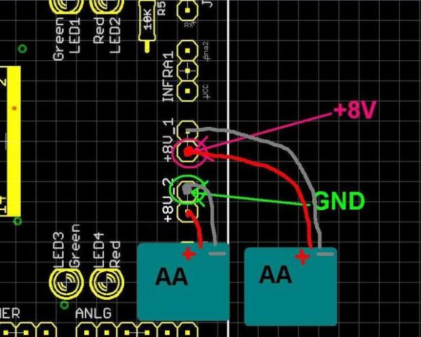
Step 9: Attach the 9Volt battery and 2 AA battery holders to their respective places using Velcro. I use Velcro because it is strong yet still allows you to remove them when they need to charge up. The 9Volt should be mounted on the top level in front of the Arduino. The 2 AA battery holders should go behind the motors ( just look at the 3D model in SketchUp to see where everything goes). A quick note on the batteries, make sure that you use 1.2volt AA rechargeable cells (most rechargeable NiMH are 1.2V), if you use standard 1.5volt alkalies that could dammage the motors because they are not rated for 9 volts (6batteries * 1.5 volts =9 where as 6*1.2= 7.2 volts)
Step 10: Time to add the “third wheel” AKA caster AKA half of a ping pong ball or other slick-surfaced sphere thats about the same size as a ping pong ball. Take either of the two things mentioned above and split it in two, you can use your favorite splitting tool be it hacksaw or guillotine… Now all thats left is to fill it with something like hot glue (thats what I used) and stick it to the bottom layer base. You can make out in the picture where I put mine, it doesn’t matter really just as long as it provides support for the other two wheels.
Step 11: Pat your self on the back, you’re doing a good job, and you’re more than half way through. On to the electronics!
For more detail: Make a wall avoiding Robot!