LEDs are great. But with any project there comes a point where flashing is simply not enough. For these cases an RGB (Red, Green, BLue) LED is the answer.
With an RGB LED you’ll be able to produce any colour glow your heart desires.
At first using an RGB LED seems quite complex, but it quite quickly becomes clear that its no more difficult than controlling one of their single colour counter parts.
What follows is a quick guide to get you started controlling an RGB LED first with wires then with an Arduino microcontroller.
If you’d like to jump ahead to any part here’s your chance.
Step 1 The Parts
Step 2 Testing
Step 3 Arduino Controlled Example Circuit
Step 4 Digital Control of Colour
Step 5 Analog Control of Colour
(Shamless Plug)
Interested in getting a few RGB LEDs to play around with and in the UK? a component bundle can be bought at our online store oomlout.co.uk
Step 1: Parts
Only a few parts are required.
RGB LED (common anode)
-
- A common anode RGB LED is nothing more complicated than three one colour LEDs (one red, one green, and one blue) housed in a single package.
- Rather than having 6 leads (a cathode and anode for each LED) it has only 4 one cathode for each colour, and one common anode. (see the schematic diagram below)
- A common anode RGB LED is the most popular type. It is most commonly found in either a 5mm bulb size or as a 5mm pirahna form factor.
Current Limiting Resistors (270 ohm) (red-purple-brown)
-
- Most LEDs are designed to work with a voltage between 1.5v and 3v. As most microcontrollers (including the Arduino) operate on 5 volts a current limiting resistor is required.
- Consult your LEDs datasheet for maximum ratings but we like to use 270 ohm resistors. This limits the current to ~20mA, well within most LEDs and microcontroller ratings.
Arduino Microcontroller & Breadboard
- A great open source microcontroller platform (for more details visit arduino.cc)
Step 2: Testing
Before we connect our RGB LED to our Arduino it’s a good idea to give it a test.
Consult your RGB LEDs datasheet for its pin-out or below are the two most common RGB LED form factors and pin-outs.
Wire up the Test Schematic (below)
- Plug the RGB LED into your breadboard
- Connect a current limiting resistor to each of the three cathodes
- Connect the common anode to 5V (5 volts)
- Test each color by connecting its current limiting resistor to ground (GND)
- Experiment with colour mixing a little by powering multiple elements at once
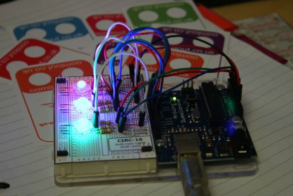
Step 3: Example Circuit
Time to move on to controlling your RGB LEDs with an Arduino.
For the example code to follow you’ll need three RGB LEDs and 9 current limiting resistors (avaliable for purchase in the UK from oomlout.co.uk )
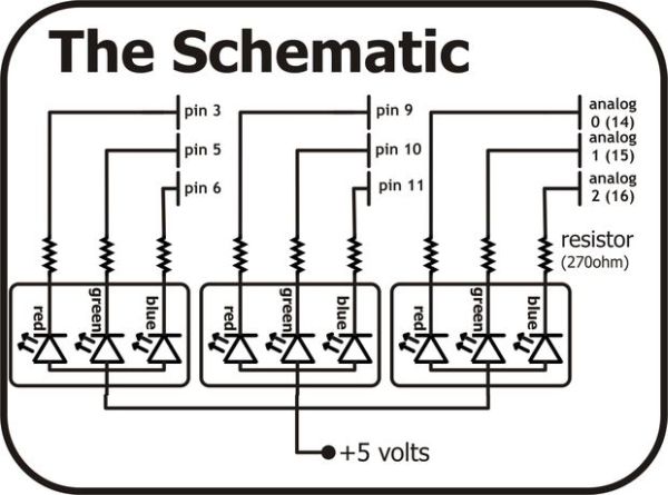
Wire up the circuit below.
There are two ways to do this. For the more advanced consult the schematic below.
Or for the less advanced you can download a breadboard layout sheet (the pdf below). Print this out and lay it over your breadboard for convenient component placement.6
Step 4: Digital Arduino Code
It is possible to control an RGB LED digitally. This requires 3 digital pins for each LED and allows for 7 colours to be displayed (Red, Green, Blue, Yellow, Cyan, Magenta, White).
But don’t take our word for it download the code below and get playing. To do this simply…
- Copy the code below and paste it into a an empty Arduino sketch.
- Compile and upload the sketch to your Arduino board.
- Enjoy as your three LEDs light up Red, Green, and Blue.
- If you go to the loop() section of the code under example 1 you can see where you change the colors. Try a few other variations
- To see how we control each LED look at the setColor() function.
- Next comment out (add //) to the three lines of example 1.
- Un-comment (delete //) from in front of every line in the Example 2 section of the loop() code
- Upload this to your board and watch as your three LEDs change colour randomly.
- Play around with the code to see how it works and make your own fun color functions.
For more detail: RGB LED Tutorial (using an Arduino) (RGBL)