This project uses an Arduino microcontroller and a laser break-beam trigger to fire via USB remote a Canon camera modified with CHDK (Canon Hack Development Kit) firmware.
Immediate influences are the high-speed flash photography triggered by sound or light project by Glacial Wanderer and the Laser Triggered High-Speed Photography instructable by Saskview. The first uses a laser break-beam and an Arduino to trigger a flash in a dark room and capture action while the second uses two 555 timer ICs to generate a signal to trigger the camera. The second method does not require a dark room.
The approach described here requires a Canon camera modified with CHDK, uses the Arduino to do the electronic heavy lifting, and does not require a dark room. My intention was to keep things relatively easy — no etching circuit boards, no cramming stuff in to small spaces &c. That said, there is some careful soldering and fabrication required but nothing beyond that.

Step 1: Blah Blah Blah
This step is here because the first step seems to appear below the Introduction. I don’t understand why and I don’t think it is a good idea.
Step 2: Parts
Parts can be obtained from any of a number of electronic suppliers. Because of the reliance on the Arduino, external parts are kept to a minimum. If you are lucky, you already have the parts lying around and the project is essentially free.
Arduino
Arduino Diecimila or comparable board. The actual board does not matter as long as you understand what the various pins do and can adjust input, output, analog, and digital pins accordingly.
Shield
In the interest of keeping this relatively simple, I built this on a Proto Shield for Arduino from Adafruit Industries outfitted with a tiny breadboard. Again, this is optional but makes things easier.
Electronic components
The electronic components need depend on one another — the resistors for the LEDs depend on the LEDs, the potentiometer depends on itself, the resistors for the voltage dividers depend on the LSR and the laser. Because of this, exact values are not given below.
Resistors
LEDs
Light-sensitive resistor
Potentiometer – linear taper is best
Miscellaneous
Similarly, the particulars of the following components are not critical. Use what you have on hand or order ones you like.
Battery holder (1)
Push-button momentarily on switch (1)
Phone jack stereo 3.5mm (1)
Plug 3.5mm (1)
USB cable (1)
Laser (1)
LED holders (3)
Pin headers (many)
Heat shrink tubing
Wire
Arms
Loc-Line from ModularHose. This stuff is really fun and pretty expensive. Buy the pliers. Also, buy a lot because you will want to make other stuff using it. See the DeskSquid and GorillaPod instructables.
Step 3: CHDK
The Canon Hack Development Kit (CHDK) modifies (improves?) the firmware for many Canon cameras and adds quite incredible capabilities to relatively modest cameras. The best part is that the changes are NOT permanent, do not damage the camera, and you can use your camera as always even with the firmware upgrade in place. It probably voids the warranty.
This instructable is NOT about the CHDK and really only uses it to enable the USB triggering of the camera. It enabled my Canon a480 (simple, cheap, point and shoot) to use a USB remote trigger, among other things. See the CHDK Wiki for information about installing and using the features of CHDK on your Canon camera.
Step 4: CHDK Primer
Installing Determine whether the CHDK has been ported for your camera. Download the CHDK for your camera and install it on your memory card. It’s that easy.
Loading Start your camera in Review mode (press on the little play button; lens should not be open). Press Menu and scroll to the bottom and update the firmware.
Using Press the Program button to get into ALT mode. This is the mode in which you access the CHDK features. Once in ALT mode (which you will recognize by the text at the bottom of your screen), press the Menu button to access the CHDK features.
Note I found it difficult to understand how to install the CHDK and access it features from material on the Internet. Because the port is different for each camera and the buttons and button layout is different for each camera, names and actions are not consistent. After working with the CHDK on my camera, things came to make sense. Be patient with this part of the project.
Determine the enclosure you are going to use BEFORE you start soldering wires to parts. Locate and drill all of the holes so you can determine the shortest reasonable length for each set of wires. Also, because of the orientation of the Arduino and the location of the power jack, the position of the Arduino in the enclosure may also be determined. Take this in to account when calculating component positions and wire length.
The tin needs several sets of holes of varying diameters. I use a metal punch to mark the hole locations and brad point bits (for wood) to drill the holes. The brad point bits have a center point and two cutting edges. They won’t skate and the edges cut slowly and cleanly through the metal. Brad point bits are available from Lee Valley (among other places).
Holes in the top
The three LED’s, the push button switch, and the potentiometer all are attached to the top and need appropriately sized and spaced holes.
Holes in the right side
The Loc-Line arm holding the laser runs out the right side and needs a 1/2 inch hole and the USB trigger for the camera runs out the right side. It needs a 1/4 inch hole.
Even though the potentiometer allows one to change the timing interval, I found it more convenient to power the Arduino via USB from a laptop. This allowed me to upload a new timing range as I was taking pictures. This necessitated yet another 1/2 inch hole on the left side of the tin. To accommodate the USB plug I had to file it slightly wider.
Holes in the left side
Only one hole is needed in the left side. The Loc-Line arm holding the LSR runs out the left side and needs a 1/2 inch hole.
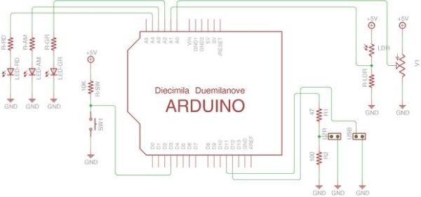
Step 6: Schematic
The image and attached file are the schematic for this project. Thank you to LinemenOwn for suggesting that they be included. I believe that this schematic is correct, but as the project was not ever turned into a board, I have not fully checked it out. Please let me know if there are any connections in error.
Step 7: Arduino Board
Begin preparing the Arduino board by laying out wires from pins to the breadboard. I used red, yellow, and green wires for the LEDs, blue for signals, red for power and black for ground. Note that there are two connections to ground and two connections to power. For a clearer view of the connections, see the schematic.
At the same time that you layout the wires, put in the resistors for the LEDs, the pull-up resistor for the switch, the single resistor for the LSR and the two resistors for the voltage divider for the laser.
In the second and third picture, I put pin headers to mark the locations of the various components. Note that the laser pin header is NOT correct in the third picture.
Note Because of the orientation of the Arduino board in the enclosure and the location of the LEDs, I used three analog input pins for the LEDs. They are configured in code to be digital pins.
Step 8: Ground Bus
To minimize space and wires on the breadboard, I fabricated a connection to ground for each side of the breadboard. After laying out the various parts on the breadboard, identify each ground connection. Take a pin header and remove all but the requisite pins. Create small looped wires that connect the remaining pins and solder.
The small loops in the wires were made using a jewelry making tool that forms wire coils.
Step 9: LEDs, Switch, Potentiometer
After determining the position of the holes in the enclosure and the location of the Arduino, figure out reasonable lengths for wires for the various components. To keep this project as simple as possible and have everything on the breadboard, I just soldered pin headers to the ends of each set of wires. These connections were reinforced with heat shrink tubing.
Note The location of these parts on the breadboard was determined in an earlier step. This step just shows the fabrication of the various parts.
Each LED requires a resistor. Determine the appropriate resistance using an LED Resistor calculator. These are readily available on the Internet.
The switch requires a 10K pull-up resistor. One of the options on the CHDK USB Remote Trigger is to fire on the falling edge. This is, apparently, faster, easier and more reliable. For this reason, use a pull-up resistor and drop the voltage when the button is pushed.
For more detail: High-speed Photography with Arduino and CHDK