Having a hardware interface to your favourite music / DJ / VJ software can really open up doors in your creativity. The most widespread form of hardware control to your PC for such applications is a MIDI based controller.
A MIDI controller can send and receive MIDI messages to your PC, allowing direct control of your software. Not only that, but the controls can generally be mapped to anything your like. So what might be a volume fader for one person can be an effect filter for another.
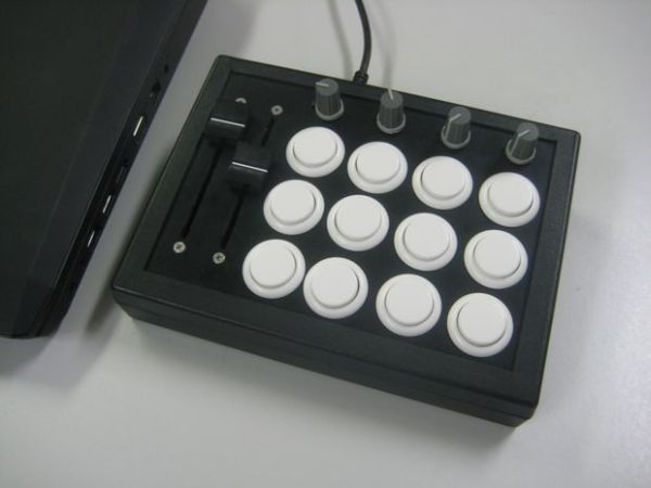
This article will describe how to build and program a custom arcade button MIDI controller, while trying to keep the price below $100. It is aimed at electronics and programming novices.
Step 1: What You’ll Need
Below is a list of components used to create the MIDI controller. The cost for this project is based on the components needed for the MIDI controller. Other tools such as a soldering iron or a power drill, or common components such as solder and wire aren’t included in the final cost. Tools which I did have to purchase are marking with italics , and their price is shown. All prices are in AUD except where indicated.
Required Components
1 x DFRduino (cheaper Arduino clone) $28.80
1 x USB cable (A to B connector, like that on a printer) $3.95
1 x Plastic enclosure $15.75
12 x Sanwa 24mm arcade buttons $26.28 (USD)
4 x 10k linear potentiometer $4.88
4 x Pot knobs $3.80
2 x 10k linear sliding potentiometer $7.54
2 x Slider knobs $2.04
5 x 10mm M3 nylon threaded spacers $2.00 (I got a bag of 25 for $9.95)
4 x 16mm countersunk M3 screws $1.00
3 x 4mm M2 self tapping screws $0.75
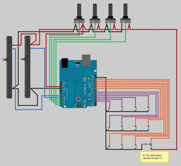
1 x 4.7 kΩ resistor $0.10
4 x stick on rubber feet $2.00
Total $98.89
All of the above can be found at most online electronics stores (I use the excellent Little Bird Electronics ), except for the Sanwa arcade buttons which can be found at arcade replacement parts stores, or from DJ TechTools . It pays to purchase one or two spare buttons and perhaps a spare potentiometer in the event that the part is faulty or you accidentally make it faulty.
Required Tools
Soldering iron
Solder
Wire stripper
Small gauge stranded wire (22 AWG), preferably in three or more different colours
About 1m of 2.5mm heat shrink
Power drill or drill press
Drill bits (2mm, 3mm, 7mm, and 11mm)
Spade bit (24mm) $12.49
Countersinking bit
10mm hexagonal wrench or spanner
Needle-nose pliers
Small riffler files $15 for pack of 10
Regular file
Phillips-head screwdriver
Step 2: Design
Before leaping into the controller design, it pays to have a look around at what’s out there in term of controllers. What appeals to you? If possible try and get your hands on some gear to get a feel for things, such as button layout and tactile feedback.
The inspiration for this article comes from DJ TechTools ‘ MIDI Fighter , specifically the grid layout of arcade buttons. The use of arcade buttons appeals to me as they are nice and large, and don’t feel mushy unlike some rubberised buttons.
So with that in mind, let’s begin the design. It helps to use some sort of diagramming software to aid in the design process such as Microsoft Visio or the open source Dia . This will help in terms of component dimensions and scale so you know everything will fit.
Design Considerations
When designing your MIDI controller, remember that an Arduino only has 6 analogue inputs for knobs/sliders and 12 digital inputs for buttons/switches (technically it has 14, but two of those will be used for serial communications to the computer). The analogue inputs can also double as digital inputs so you could have up to 18 buttons on your design, or 17 buttons and 1 slider, or 16 buttons and 2 sliders, etc down to 12 buttons and 6 sliders.
Also try to find the dimensions of all of the components you wish to use so you have a good idea of what will and won’t fit, and the clearance you’ll need to give each component. For example the sliding potentiometers I’ve chosen have a travel length of 60mm, but then there’s the extra clearance required on either side of the slider for the slider knob.
More analogue and digital inputs could be used with the aid of shift registers, multiplexers, or extra microcontrollers, but that is beyond the scope of this article.
Design 1
I initially wanted to make a copy of the MIDI Fighter, so I drew up a basic 4 x 4 grid of arcade buttons based on the arcade button’s dimensions (27mm total diameter, 24mm mounting hole). Although it looked kinda cool, I also wanted some analogue inputs such as knobs and faders. I also didn’t want to go through the hassle of cutting my own acrylic to make the case. So I decided then I’d find a plastic enclosure to house the controls and base the design around those dimensions.
Design 2
After a bit of hunting around for different enclosures, I eventually settled on this keyboard enclosure . Its dimensions are 189mm x 134mm, with a sloping height from 32mm up to 54.7mm. When choosing your enclosure make sure that your components are going to fit inside it. The mounting depth for the arcade buttons is exactly 32mm, so they will fit in the enclosure I’ve chosen.
Given this enclosure isn’t square, I went for a 5 x 3 button arrangement and squeezed in a couple of sliding potentiometers up the top. When working out how to place the sliders, make sure to leave enough room for movement of the slider knob so it doesn’t hit any other components. You’ll have to find out the dimensions of the slider knob you wish to use so you can accurately place the slider. As the enclosure is higher at the back it also provides room to mount the Arduino clone underneath the buttons and sliders.
At this stage I’d recommend printing out a 1:1 sized copy of the design to ensure the layout feels natural, and all of the components are easily reachable. My design felt good, but I felt like I was wasting the Arduino’s six analogue inputs with only two sliders.
Final Design 1
For the final design I removed the left most column of buttons and replaced it with a column of four rotary potentiometers, so now all six analogue inputs will be used. I also packed the components a bit more tightly together so they’d fit within the recess on the front panel.
Once you’re happy with your design, go ahead and order the necessary components. Remember to check the knobs you’ve chosen will actually fit the sliding/rotary potentiometers. Some rotary knobs are designed for a ‘D’ type shaft, while others are designed for shaft with 18 teeth, while others simply screw onto the shaft.
Final Design 2
After about a week all of the components arrived, but I immediately noticed the sliders were too long (the dimensions on the datasheet were incorrect so I thought they were shorter). So rather than going through the hassle of exchanging them, I tweaked the design and swapped the sliders and rotary potentiometers around. I also measured the dimensions of the enclosure recess to ensure everything fit correctly.
Step 3: Construction
Now that we have our design and the components have arrived in the mail, it’s time to start cutting holes in the enclosure.
As you probably saw in the design phase, all of the dimensions for where components are to be placed are marked out. Not only does this aid the design layout, but is also useful when it comes to marking out where to cut the enclosure. I’ve included the schematic for my final controller design. Remember to mark out any screw holes or other mounting holes (I needed some extras for each rotary potentiometer).
Based on the schematic there are three types of holes to be made; a small 7mm hole for the rotary potentiometers, a larger 24mm hole for the arcade buttons, and a long narrow groove for the sliding potentiometers. We’ll also need another small hole on the rear of the enclosure for connecting the USB cable to the Arduino board, and obviously any screw holes.
Measure and Mark Where to Cut
There are two ways to go about this step. The first is to grab a ruler and pencil and, using the schematic as a reference, mark out the center of each hole and the grooves for the sliders.
The second method (which I recently discovered on this Intructable ) is to print out a 1:1 sized copy of the schematic and stick it to the enclosure’s surface. This in effect does all of the required marking and can reduce error at the same time. Given that’s the case, I went with this second option.
Attached is a 1:1 schematic in pdf form, ready to print. When printing make sure it isn’t being scaled before being sent off to the printer. Simply cut around the dotted rectangle so the paper will fit in the recess on the front panel, then stick it down using double sided tape. To cut the paper I’d recommend grabbing a metal ruler and a safety blade, then line up the ruler with the dotted line and run the blade down its length. This way the cuts will be nice and straight. Make sure you have something protecting your work surface underneath!
Drill the Holes
When drilling the holes it’s a good idea to drill a small pilot hole first and then use the larger bits to drill the full sized holes. Start by drilling through the center of each arcade button marking on the schematic with a 2mm bit, and then do the same for the rotary potentiometer markings.
Switch over to a 7mm bit and drill through the rotary pot pilot holes to expand them. At this point I took the paper schematic off the enclosure because it was just going to get torn to shreds. Switch over to a 24mm spade bit and drill out the pilot holes for the arcade buttons. When using the spade bit remember to take it slowly to get a nice and circular hole. Make sure you have a sturdy grip or a clamp holding the enclosure lid to your work surface, else it will jump around a bit when drilling.
Getting Into the Groove
Grab a second print out of the schematic and stick it to the enclosure lid. Using a 3mm bit, drill out the screw holes for the sliding potentiometers. Now comes the tedious/fun part. To make the groove, drill a series of holes all the way down the length of the groove. The holes should be separated by no more than 1-2mm. Take your time and try to keep the holes as straight as possible.
After all of the holes have been drilled, use the countersinking bit to countersink the screw holes for the sliding potentiometers. These holes need to be countersunk otherwise the slider knob would hit the exposed screw head when it reaches the top or bottom of the groove. When drilling these I only drilled out a small amount at a time. Then I’d grab one of the countersunk screws and put it through the hole to check if the head was flush with the top of the lid. Repeat this as many times as necessary to get the nicest finish possible.
Now use the riffler files to remove the plastic between the holes which run the length of the slider groove. Also gently file the inner sides of the groove so it’s as straight and as smooth as possible.
Step 4: Mounting
This part is fairly straight forward, but is important as it will reveal any problems made in the previous step.
Each of the arcade buttons will just push into their hole and snap into place. Try and mount them so the legs are vertical relative to the enclosure. This will make wiring a bit easier in the next step.
The rotary potentiometers have a washer and hexagonal nut screwed on to them. Remove both, and then insert the potentiometer through their corresponding holes from the underside of the enclosure lid. Hold it in place, and then from the top side slide the washer and screw the nut down around the potentiometer shaft using the hexagonal spanner. Ensure that each potentiometer is facing the same direction when screwing them in. If the pots you have are like mine, there’s a small metal guide which should fit into the little 2mm hole next to the potentiometer hole. This helps to stop it from twisting loose.
From the top side of the lid, insert the four 16mm M3 screws into the holes above and below the sliding potentiometers. On the underside screw a 10mm spacer onto each screw until it just touches the plastic. There should be around 2mm of exposed thread on the bottom of the screw. After doing this for all four screws, get one of the sliding potentiometers and line it up with two of the screws on the underside of the lid. Ensure the slider is oriented so the two legs which are close together are toward the bottom of the enclosure (the narrow end).
Using a screwdriver screw each of the screws into the potentiometers mounting holes. Don’t over tighten otherwise you’ll start boring the drill through the plastic lid.
What About the Arduino?
I’m glad you asked! With everything mounted in the enclosure lid, attempt to fit it to the enclosure base (without the Arduino inside). You may find (like I did) that the sliding potentiometer legs are slightly too long to fit in the enclosure when it’s closed. I simply used a pair of needle nose pliers and bent each leg at about half of length at a 90 degree angle.
Now that everything fits grab the Arduino and place it inside the case towards the back, with the USB socket facing the back. I found that I could actually line up one of the enclosure’s PCB stand-offs with the hole nearest the USB on the Arduino, which would mean the USB socket sat flush with the back wall once a hole had been cut.
Gently close the lid to ensure none of the components touch the Arduino. If the components do touch it, shift the Arduino to another location and try again. You may find that the arcade button legs get in the way of the Arduino. Rather than bending them like the slider legs, pop the arcade button out and insert it again at a different angle.
More Drilling and Filing?
This is the last of it, I promise! Once you’ve decided on the location of the Arduino, mark out where to cut a hole for the USB socket. The USB socket itself is about 12mm wide and 11mm high. Using the 11mm drill bit, drill an opening straight down on to the edge of the enclosure until the tip of the drill is about half way down.
Take your regular file and square up the edges of the opening. Sit your Arduino’s USB socket in the opening to check if it fits. If not, file away some more. Repeat this process until the USB socket sits nicely in the rectangular opening.
You will also need to file a small section out of the bottom edge of the enclosure lid to accommodate the top of the USB socket. Place the lid onto the enclosure base and mark out where to file based on the opening in the base. Take out the components from the lid if you haven’t already, then file away about 2mm. Check the USB socket fits with the Arduino inside the case.
One Last Thing
We need a couple of stand-offs for the Arduino PCB. I chose to cut in half one of the 10mm nylon spacers, and then glue each half to the base of the enclosure where the remaining screws for the Arduino needed to go.
For more detail: Arcade Button MIDI Controller