Caveat Emptor: (I don’t want to put you off building one but I also don’t want you to be disappointed.) This Instructable is now 2 years old. Many of the parts it uses are out of date (there’s no drop-in replacement for the now-discontinued gyro, for example) and I’ve had reports that the code is hard to compile. If you’re not comfortable with the principles behind the electronics, code and the math’s involved in PID control then you probably shouldn’t attempt to build one. Also, it’s a tricky project to debug once built so it’s really not a good first project. If you’re not happy to spend 2 days watching your bot list, jiggle, zoom across the room and fall over before you get it to balance then steer clear!
This instructable shows how I built my ArduRoller balance bot. It balances quite well on the spot and responds to most knocks pretty quickly but sometimes giving it a more gentle push sends it gliding across the room at a constant speed. I’m still working on that.
There’s a video of the bot in action at http://www.flickr.com/photos/fasaxc/5944650602/.
Step 1: Parts
Here are the parts I used:
1 x Arduino Uno
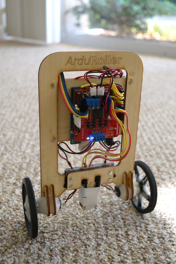
1 x Sparkfun Ardumoto motor driver shield
1 x Sparkfun BlueSmirf Bluetooth modem
1 x 150 degree/s gyro
1 x 1.7g Accelerometer
2 x Arduino header kits
2 x screw terminals
2 x 24:1 gear motor
1 x set of 70mm wheels
2 x JST connectors
2 x LiPo batteries
1 x basic LiPo charger
3 x Multi-turn 10k potentiometers
1 x SPST switch (Radioshack)
1 x Laser-cut bamboo chassis via Ponoko (link should allow you to make one from my shared design)
1 x LED
1 x Normally-open push switch
1 x packet of Sugru to make the bumber
Assorted M2-04 machine screws (6mm – 16mm) (found on Amazon)
M2-04 nuts to match machine screws above
Assorted straight and right-angle break-away headers
Assorted jumper wires
Solid core wire
Stranded core wire
Instamorph (aka Polymorph) low-melt-point thermoplastic
Notes:
Chassis: the motors didn’t quite fit the mounts I made so I had to sand them down and rebuild them with instamorph. I think the sensor bundle suffers from too much vibration, it might have been better to make it more solid rather than sticking out as it does.
Accelerometer: I originally tried building the bot with only an accelerometer for tilt sensing and no gyro. It turns out that approach is a non-starter — the accelerometer gets overwhelmed by the acceleration due to the motors so it can’t be used to estimate tilt while the bot is accelerating. OTOH, using only a gyro would make the bot susceptible to drift over time so you really need both.
Gyro: I used a 150 degree/s rate gyro. From looking at the telemetry from my bot, I’m pretty sure it sometimes clip if you give the bot a knocks so if I was starting over I’d probably look for a 300 degree/s model.
Wheels: the wheels are a little fragile, after a few knocks I noticed cracks around the axle so I strengthened them with instamorph.
Motors: I also tried sparkfun’s 100:1 gear motors but they weren’t fast enough. The 24:1 versions have plenty of torque and speed.
Bluetooth: I use the Bluetooth modem for telemetry right now but I’m also planning to use it for remote control from my Android phone. If you omit it then the robot will still work but tuning it will be harder.
Pots: I added 3 10k multi-turn pots to the design to allow me to easily tweak internal values. Using 3 might have been overkill since I tend to tweak only one thing at once.
Instamorph: Amazing stuff. It’s a tough, white plastic (resembling solid nylon) at room temperature but if you heat it in boiling water it turns into a pliable goo that’s really easy to work with your hands. A heat gun is great for working with it too, allowing you to melt small areas.
Step 2: Overall design
This step covers the overall design of the bot. I’ll try to explain what each of the parts is for:
The brain of the system is the Arduino Uno, which contains an AVR microcontroller running at 16MHz.
1000 times per second, the microcontroller reads the current state of the gyroscope and accelerometer; updates its internal model of the bot and from that model decides how fast to run the motors to best balance the bot. (The code is all shared on my Github repo .)
The gyro is a rate gyro, which means that its output is proportional to the current rate of rotation. To estimate the current tilt, the microcontroller has to sum the incoming values, which it reads using an analog to digital converter. Unfortunately, no gyro or ADC is perfect, resulting in errors in the summation that tend to grow over time. If the bot used only a gyro to try to balance then its idea of “up” would slowly drift over time and it’d eventually fall over.
To counteract the gyro’s tendency to drift, the bot uses a 2D accelerometer to measure the direction of gravity. When summing the gyro values it adds in a tiny fraction of the accelerometer estimate into the calculation. Just enough to balance out the drift. It can’t add too much because the accelerometer is a very noisy sensor – it picks up vibration from the wheels and the acceleration of the motors.
The gyro and accelerometer are mounted on the axis of rotation of the wheels to get the best signal.
Once the microcontroller has decided how fast to run the motors it uses pulse width modulation to vary their speed and drives them through the Ardumoto shield. The shield is necessary because the motors draw far more current than the microcontroller can supply on its own.
The BlueSMIRF module provides serial-over-Bluetooth, allowing the bot to communicate in both directions with another Bluetooth-enabled device. I use my Android phone to relay the serial data to the console over the Android Debug Bridge. I’m also planning to send signals the other way to use my phone as a remote control.
Step 3: Chassis

I designed the chassis using Inkscape on Linux and used Ponoko for laser cutting. The SVG version is in my Github repository and I’ve published it on Ponoko .
I was pretty pleased with how it turned out given it was my first try at using Ponoko. The only part that didn’t work so well was the motor mount, which I had to sand down and augment with Instamorph.
Using Ponoko, the wood grain runs left-to-right so some parts need to be placed sideways. The laser cutter is incredibly precise and does a great job on screw holes.
Be sure to read Ponoko’s design rules if you intend to modify the chassis design. There are gotchas like needing to put “nodes” in push-fit slots to take account of material differences and the fact that the laser removes 0.2mm around your line.
Step 4: [Update] Bumper