NOTE:
This instructable is now slightly old and a better machine has been made with lower cost parts and much better software that automatically allows you to “pair” new cards with new tracks as they are added to the iPod playlist.
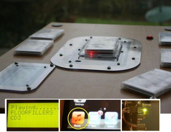
iPod playback track selection simply by putting RFID “bricks” on a table.
– An iPod Touch controlled by Arduino via the serial protocol intended for use by docking stations and other peripherals.
– RFID (Radio Frequency Identification) cards are embedded in small plastic blocks with album cover art on the face of each block.
– Advanced serial mode is used, giving 2-way communication between Arduino and iPod and ability to select individual tracks by number.
– All built into a small wooden table.
– Place an RFID “block” in the centre of the table and the selected album plays automatically, no conventional controls or menus at all.
Why?
I was trying to make a music player for a disabled child who is unable to load and operate a CD player or negotiate the small buttons and menus of mp3 players. Original plan was to make a basic big-button mp3 player with just forward/back buttons and maybe 100 songs on it. I then found this website by David Findlay which documents his experiments in acquiring control of an iPod via its serial connection: http://davidfindlay.org/weblog/files/tag-ipod.php
Before going further I must say David has helped me a lot with this, completely rewriting the code after seeing my clumsy attempts at merging RFID reader code with his Advanced Remote serial code.
There are several serial protocols which the iPod can understand. The big advantage of the “Advanced” mode is that instead of just giving you virtual forward/back, volume buttons and so on, it allows you to select tracks from a playlist by their number.
– Therefore the Arduino can select the first track on an album and the playlist will start playing from that point onwards.
– Therefore I can use an RFID card, one for each album in the iPod playlist, to “tell” the iPod the track number to start playing from.
– Therefore it should work, so I had a go at building it.
Who might use it?
The child I made it for has it playing all day long, so it has been a big success. It might also benefit anyone with impaired vision, hand tremor, poor dexterity, the old and also the very young. The RFID blocks could even have Braille titles on them potentially. Also good for total technophobes I suppose.
Shopping list
1) Arduino Mega (the multiple serial ports are quite handy). Good news is you can use the cheaper one if you like – the 1280
http://arduino.cc/en/Main/ArduinoBoardMega Approx $40 for a Mega 1280 clone
2) Parallax Serial RFID reader. http://www.parallax.com/tabid/768/ProductID/114/Default.aspx $39.99
3) A serial 4 x 20 LCD display (optional), shows you which album is playing. Example: http://www.sparkfun.com/products/9568 $29.95
4) A PodGizmo Breakout board. This is a 30 pin plug for the iPod with solder pads brought out on a board for each pin. http://www.sparkfun.com/products/8295 $14.95
5) Sparkfun logic level converter; Arduino uses 5V for everything, iPod uses 3.3V so this does the conversion for serial communication lines. http://www.sparkfun.com/products/8745 $1.95
6) RFID cards. One for each of your albums (or even one per song if you prefer). Can get them on well known auction site in bulk. Make sure you have correct type – the EM4100 family. About $1 – $1.50 each.
7) I used cheap plastic business card holders to contain each RFID card, album cover label and filler cardboard to convert the RFID cards into small tough “blocks” suitable for small hands. Again available in bulk on well known auction website. Approx $1 for two.
8) A 500kOhm resistor
9) A push to make button (used as Arduino reset button).
10) Power supply for Arduino (Wall-wart). Approx $10.
Step 1: How it works
The blue RFID reader has a range of about 4 inches so it has been fixed by 4 small bolts and spacers (cut from plastic tube) to the underside of a sheet of polycarbonate cut into an artistic oval using a jigsaw.
I used a project box which has a lid on the top held by screws which screw down into main box. The polycarbonate oval now forms the new “lid” for this box and 6 screws that came with the project box now hold it to underside of the polycarbonate.
The whole assembly is then self contained and fits into your table / box / cabinet / Star-Trek control panel of choice by simply dropping it down over a hole cut into the top surface. The project box sits in the hole while the polycarbonate is held down with self-tapping screws that go into the wood around the edges.
This makes it easy to take apart to fix any problems.
Step 2: How it works
Introduction
This shows the general idea.
A project box holds the Arduino Mega. A multicore cable comes out and connects to the iPod Touch I am using.
You can see the strange connector at the base of the iPod. This is the PodGizmo breakout board which has a plug one side for the iPod and 30 solder holes on a circuit board the other side. This means you can solder up the wires without needing a microscope.
The Parallax RFID reader is the blue flat object seen fixed to the underside of the open polycarbonate “lid” and the red button is an Arduino reset button which you need to get it talking to the iPod at initial startup.
The table is actually a small cabinet bought as a flat pack item from a really low cost furniture store (since the first thing I did on getting home was cut a hole in the top).
Step 4: Introduction (2)
Introduction (2)
Top view.
I have a little tray made from the lid of a small project box which the RFID “bricks” are placed into. This keeps them located exactly above the RFID reader.
A few of the spare “bricks” can also be seen. The RFID reader simply detects the nearest one with the strongest signal. In this application the short range of the reader is actually an advantage.
There is also an LCD display top left which tells you which album is playing and so on.
This is not essential for the device to work however, it just looks nice.
Step 5: About RFID cards
About RFID cards
RFID cards have a coil of wire in them and a radio transmitter. The reader induces a current in the wire coil which then momentarily powers the radio transmitter. This sends a 10 digit code to the RFID reader (and so to the Arduino). Each card has a unique number.
Therefore the software in the Arduino can work as follows:
“If I see number XXXXXYYYYY on the RFID reader, I must instruct the iPod to start playing track number X in the playlist.”
It will do this every time it sees that particular card.
Later on I will show how the numbers are discovered for each card, it is best to just write the number on the back of each one.
Each card represents the first track of each album in the playlist, and the cover art from each CD is put on the front as a label.
Here are a few spare “bricks” on the floor waiting to be chosen next!
Step 6: Creating a link to the iPod (1)
Creating a link to the iPod (1)
Here is the PodGizmo breakout board.
On the left is a picture of it and on the right I have altered it slightly to make the pin solder holes more obvious.
This plugs into the base of the iPod.
We do not use all 30 wires (phew!) but we do need some for:
a) Serial communication between Arduino and iPod.
b) To carry audio output to our line-out sockets and headphone socket.
c) Pin 21 has to be connected to GND (ground) via a 500kOhm resistor to “tell” the iPod it has been connected to an external device.
The secret is to take each aspect in turn, breaking the task into small chunks.
Step 7: Create a link to the iPod (2)
Get Sparkfun voltage converter board
The serial data from the Arduino is at 5V, however the iPod does not like this, it operates at 3.3V.
This board from Sparkfun does the job for you, allowing the data to flow but changing the voltages along the way to keep both sides happy.
You can see one side is labelled HV (high voltage, i.e. 5V) and the other LV (low voltage, i.e. 3.3V).
Step 8: Connection to iPod
Connection to iPod
This shows the PodGizmo breakout board with wires soldered to it and plugged into the iPod.
This is designed for experimentation but is not very elegant. They do a smaller one where all the wires will fit into the plug itself, but I cannot get it here in the UK.
Step 9: Create link to the iPod (3)
How to connect these to the Arduino Mega
OK it had to happen, some circuit diagrams.
This part deals with how the Arduino talks to the iPod via serial connection. Notice how the voltage converter has been used to keep the Arduino side at 5V and the iPod side at 3.3V
Solder it up exactly as shown here. Make sure the voltage converter is not back to front and so on.
Soldering has to be neat here else whole thing will be totally unreliable. I rub the solder holes very slightly with fine emery paper wrapped around a tiny screwdriver first, to make sure the solder takes and flows easily, but that is just my own preference.
*******I SUGGEST USING AN OLDER iPOD for this project as if you make a soldering mistake you could damage your expensive new iPhone for example. I used an ex-demo iPod Touch 2nd generation
Step 10: How to connect the RFID receiver (1)
This has 4 pins on it.
VCC is the one you supply +5V to from the 5V pin on the Mega.
GND is connected to any of the GND pins on the Mega.
/ENABLE is connected to digital pin 2 on the Mega so the Arduino can “enable” the reader to look for new RFID cards at set time intervals.
SOUT is the data output
For wiring diagram see next page
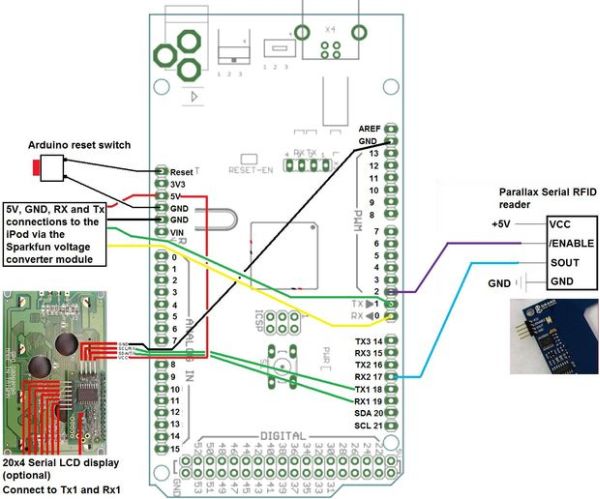
Step 11: How to connect the RFID receiver (2)
How to connect the RFID receiver (2):
(Wires for +5V power and GND between Arduino and the RFID reader are not shown in the diagram).
Also shows the LCD and also the Reset button
Reset button brings the “reset” pin to GND when pressed.
SOUT on the RFID reader connects to RX2 on the Mega (one of its serial ports).
The optional LCD display is also shown. This has a +5V supply, a wire to GND, and 2 remaining wires for serial communication to TX1 and RX1 on the Mega.
NOTE: If on first startup nothing happens, switch the RX1 and TX1 wires around as it is incredibly easy to get them mixed up
Step 12: Box of electronics
Box of electronics
Here it all is looking rather untidy.
Mega visible on right.
Lower middle is the small voltage converter module.
Top left are two 10K Ohm potentiometers. These adjust the volume to the headphones (one for each channel).
Step 13: Serial LCD display
Serial LCD display.
Displays album title, then reads name of track currently playing from the iPod and displays it along with name of the artist.
Step 14: How to get sound out of iPod (1)
How to get sound out of the iPod (1)
Photo of the phono sockets for the cable to HiFi amplifier.
OK, we need some sound out of this thing somehow.
The iPod thinks it is connected to an external device via a docking station. Therefore it sends its audio out the “line-out” pins NOT the iPod headphone socket.
The line-out audio is wired up to two phono sockets shown here. A suitable cable with two phono plugs on each end is then used to connect it to a HiFi amplifier if that is what you want to do.
You can connect the line out wires to a headphone socket, and indeed I have run them from these line-out phono sockets to a headphone socket, but it is very loud, hence the presence of the two 10K Ohm potentiometers to adjust each side of the headphone volume.
For more detail: Magic Music Table No menus, no buttons