Hi from Italy
Although many watches are created binary, my project was inspired mainly to this:
http:// http://www.instructables.com/id/LED-Binary-Clock-1/, very smart and funny.
I tried to improve the design and to add something personal.
I think it’s a good result at the end.
The project is not difficult, requires patience, it requires a little knowledge of electronics and the use of Arduino.
Step 1: List of materials
–n.1 IKEA frame called “Ribba” 13×18 cm
-LED to mark hours and minutes (You have seen the first images of the LEDs that there are different colors, but of course you can change them as you like, now is the reference of the project.):
n.8 green 5 mm
n.3 red 5mm
n.2 yellow 5 mm
–LED to light the words “Hours Minutes”
n.7 white 5mm
–LED to light the numbers 1/2/4/8
n.4 pink 5mm
–LED to light the words “binary clock”
n.4 pink 3 mm
-n.24 Resistor 220 ohm (for 5mm led)
-n.4 Resistor 150 ohm (for 3mm led)
-CartonBoard thicker to make LED holder (we will Insert the cartonBoard between the glass and the bottom of the frame supporting)
-Some acetate (4-5) sheets (for inkjet or laserPrint) to create the mask
-a flat wire 26 wire
-3 micro button to set hours and minutes and on/off
-A small piece of prototyping PCB to make the shield (see later)
-Some double strip
-n.1 Arduino Uno/2009 or clone or self made. I’ve used one Luigino assembled by me
-Power supply 6V 500ma or other Arduino compatible.
Step 2: Goals
At the beginning we try to understand how reading the time, I think it’s important to understand the electronic connections.
The first two columns correspond to the hours, the third and fourth to the minutes.
The first column are the units of hours and the second the tens, the same thing for minutes.
For each column must add the corresponding value (displayed on the right with the numbers 1-2-4-8) and reading the following you have the time in 24h format.
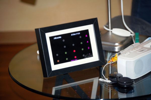
It ‘very simple, we take the example of the first photo you see above:
HOURS
-first yellow spot= 10
-3 green spot= 7 (4+2+1)
MINUTES
-first and third red spot= 50 (40+10)
-2 green spot= 5 (4+1)
So , 17:55 ok?
So we have to create a set of LEDs to display the time in this way, the circuit and the program will be managed by Arduino.
The remaining lights (Hours, Minutes, 1/2/3/4, binary clock) are embellishment for the clock (also improve the general understanding) but still managed by Arduino.
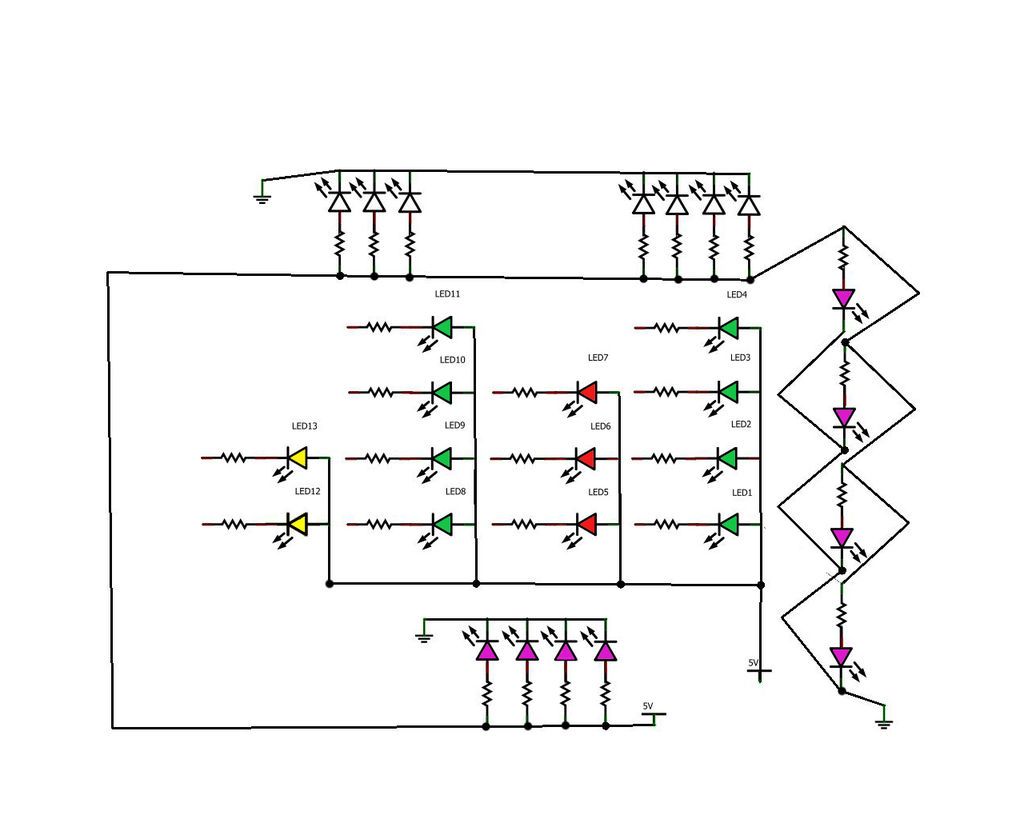
Step 3: Schematic
This is the pattern that we must achieve.
ALL LEDS ARE CONNECTED TO A DIGITAL PIN BY ARDUINO
ALL MICRO BUTTONS ARE CONNECTED TO A ANALOG PIN BY ARDUINO
All LEDs who rule the time are connected with the cathode (negative -short leg) and a 220 ohm resistor to digital pin, all the anodes (positive-long leg) are connected together with 5v by Arduino. (see photos in the next step)
All LEDs embellishment (words “Hours / Minutes / BinaryClock”) are connected in parallel and that all the anodes are connected together with a resistor and goes to the PIN 0 (see photos in the next step), all the cathodes are connected together and go to the GND
The micro buttons are connected to one side to the Analog pin and the other side to GND.
More precisely (see the schematic picture):
LED1-LED2-LED3-LED4 to ARDUINO DIGITALS PIN1-PIN2-PIN3-PIN4
units of Minutes
LED5-LED6-LED7 to ARDUINO DIGITALS PIN5-PIN6-PIN7
tens of Minutes
LED8-LED9-LED10-LED11 to ARDUINO DIGITALS PIN8-PIN9-PIN10-PIN11
units on Hours
LED12-LED13 to ARDUINO DIGITALS PIN12-PIN13
tens of Hours
LED14/LED15/LED16/LED17/LED18/LED19/LED20/LED21/LED22/LED23/LED24/LED25/LED26/LED27/LED28
to ARDUINO DIGITAL PIN 0 (all together)
MICRO BUTTON
As you read above we will have 3 micro button.
1th Button will change minutes, adding one for each time you press it. ANALOG PIN 0
2th Button will change hours, adding one for each time you press it. ANALOG PIN 5
3th Button (optional) will turn ON/OFF the clock LEDs, but keep counting the time. ANALOG PIN 4
Major Components in Project
Parts
Arduino Uno
LED
For more detail: My Arduino Binary Clock