Here we will be learning how to make a color sensor. my model consists of three cardboard compartments containing an LED – one red, one blue, and one green – and an OP550B phototransistor. The LED’s shine simultaneously on a solid colored card. The phototransistors are connected to an Arduino Uno, which converts the relative amounts of measured reflected light of each color into RGB components which are used to light an RGB LED the same color as the card.
Video of it working:
Step 1: Materials
To make this color sensor, you will need:
* Red LED
* Green LED
* Blue LED
* RGB LED
* 3 phototransistors – I used OP550B’s, but others could be used.
* 6 220 ohm resistors
* 3 10k ohm resistors
* Cardboard or some other divider to separate the LED’s
* Breadboard or circuit board and soldering materials
* wires
* Arduino and usb cord
* Computer
* Electrical tape
* Cards of various colors – I used index cards covered in electrical tape of different colors.
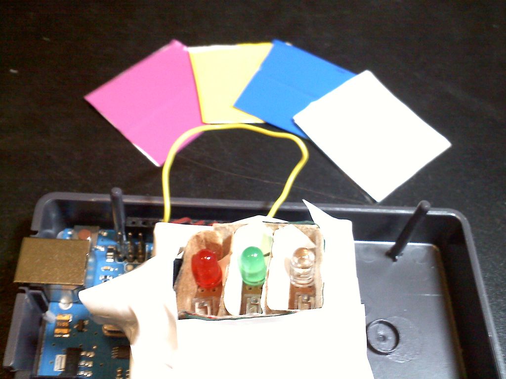
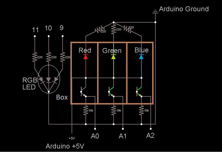
Step 2: Step 1: Create the Circuit Board
* Make sure to leave enough room to superimpose the dividers – in my case a compartmentalized cardboard box – later.
Step 3: Step 2: Make the Light-Proof Box and Cards
B. Attach the outer box to the circuit board. I used a hot glue gun to do this, but clay or another opaque, malleable substance would be more effective for keeping light out.
C. Cut two more thin strips of cardboard the same height as the outer box, and just long enough to fit snugly inside the box.
D. Attach these inside the box to separate the three LED/transistor pairs. I taped the sides and bottom of the inner strips to the inside sides of the box with white electrical tape.
E. Cover the bottom of the circuit board with electrical tape to prevent outside light from getting through the holes in the circuit board.
F. Enclose the RGB LED in a light proof material like electrical tape to prevent it from interfering with measurements (see diagram).
G. Cover the sides of the box with electrical tape to reduce outside light interference.
H. Cut out several squares of index card big enough to cover the box. Cover each side with a single color of electrical tape.
Step 4: Step 3: Write Code
Here is my Arduino code. You will need to calibrate the const values based on how much light is in the room – comment out the indicated portion of the loop() method and note the RGB values it displays for different colored cards. Store those RGB values in the ICOLOR const int[]’s at the beginning of the script. If you did a good job of light-proofing the box, the same RGB values should work with various levels of background light.
/**Runs a color sensor on the Arduino
* Start the program while showing it the white card. When the RGB LED turns off,
* switch (quickly) to the black card. After the RGB LED flashes white, it is ready.
*/
//pin identifiers
int blue = A2;
int green = A1;
int red = A0;
int redOut = 9;
int greenOut = 10;
int blueOut = 11;
//counts the number of loops – used to time events
int count = 0;
//stores the current RGB input
int out[3];
//ICOLOR = RGB input from transistor that is that color.
//COLOR = RGB output to make RGB LED show that color
int IWHITE[3] = {175,48,455}; int WHITE[3] = {224,226,243};
int IBLACK[3] = {42,5,20}; int OFF[3] = {0,0,0};
int IRED[3] = {145,15,38}; int RED[3] = {200,0,0};
int IYELLOW[3] = {175,40,60}; int YELLOW[3] = {255,150,0};
int IMAGENTA[3] = {150,16,83}; int MAGENTA[3] = {200,0,200};
int IBLUE[3] = {57,7,160}; int BLUE[3] = {0,0,200};
int IGREEN[3] = {41,6,50}; int GREEN[3] = {0,200,0};
int NONE[3];
//[0] of these is the min, [1] is the max.
int redConvert[2];
int greenConvert[2];
int blueConvert[2];
//reads in the current color
int* readColor(){
int ret[3];
ret[0] = analogRead(red);
ret[1] = analogRead(green);
ret[2] = analogRead(blue);
return ret;
}
//checks that each element in color1 is within dev of
//the corresponding element in refColor
boolean inRange(int color1[], int refColor[], int dev){
return (abs(color1[0] – refColor[0]) <= dev) &&
abs(color1[1] – refColor[1]) <= dev &&
abs(color1[2] – refColor[2]) <= dev;
}
//sets the RGB LED color
void setColor(int color[]){
analogWrite(redOut, color[0]);
analogWrite(greenOut, color[1]);
analogWrite(blueOut, color[2]);
}
//determines values for black and white
void calibrate(){
setColor(RED);
delay(500);
setColor(GREEN);
delay(500);
setColor(BLUE);
delay(500);
setColor(WHITE);
int redSum = 0;
int greenSum = 0;
int blueSum = 0;
for(int i = 1; i <= 5; i++){
redSum += analogRead(red);
greenSum += analogRead(green);
blueSum += analogRead(blue);
delay(333);
}
int whiteCal[3] = {redSum/5,greenSum/5,blueSum/5};
redSum = blueSum = greenSum = 0;
setColor(OFF);
Serial.print(“white Cal (RGB): “);
Serial.print(whiteCal[0]);
Serial.print(” “);
Serial.print(whiteCal[1]);
Serial.print(” “);
Serial.println(whiteCal[2]);
Serial.println(“insert black card”);
while(inRange(readColor(),whiteCal,50)){
delay(1000);
Serial.print(“red green blue: “);
Serial.print(analogRead(red));
Serial.print(” “);
Serial.print(analogRead(green));
Serial.print(” “);
Serial.println(analogRead(blue));
//setColor(out);
}
Serial.println(“new card detected – I hope it’s black”);
delay(5000);
for(int i = 1; i <= 5; i++){
redSum += analogRead(red);
greenSum += analogRead(green);
blueSum += analogRead(blue);
delay(100);
}
int blackCal[3] = {redSum/5,greenSum/5,blueSum/5};
Serial.print(“black Cal (RGB): “);
Serial.print(blackCal[0]);
Serial.print(” “);
Serial.print(blackCal[1]);
Serial.print(” “);
Serial.println(blackCal[2]);
//calculate conversion functions
redConvert[0] = blackCal[0];
redConvert[1] = whiteCal[0];
greenConvert[0] = blackCal[1];
greenConvert[1] = whiteCal[1];
blueConvert[0] = blackCal[2];
blueConvert[1] = whiteCal[2];
}
//runs calibration routine and turns the light white before
//starting loop
void setup(){
Serial.begin(9600);
calibrate();
setColor(WHITE);
delay(1000);
}
void loop(){
//reads in new values
out[0] = analogRead(red);//0-1024
out[1] = analogRead(green);
out[2] = analogRead(blue);
//update RGB LED and print output less frequently
if(count % 5000 == 0){
Serial.print(“red green blue: “);
Serial.print(out[0]);
Serial.print(” “);
Serial.print(out[1]);
Serial.print(” “);
Serial.println(out[2]);
//comment out the rest of this loop to just display values and not use the RGB LED
if(inRange(out,IWHITE,10)){
Serial.println(“White!”);
setColor(WHITE);
}
else if(inRange(out,IRED,10)){
Serial.println(“Red!”);
setColor(RED);
}
else if(inRange(out,IBLUE,10)){
Serial.println(“Blue!”);
setColor(BLUE);
}
else if(inRange(out,IYELLOW,10)){
Serial.println(“Yellow!”);
setColor(YELLOW);
}
else if(inRange(out,IMAGENTA,10)){
Serial.println(“Magenta!”);
setColor(MAGENTA);
}
else if(inRange(out,IGREEN,10)){
Serial.println(“Green!”);
setColor(GREEN);
}
else setColor(OFF);
}
count++;
}