Part 1: Build an Arduino on a Board
Part 2: Build the motor-controller & body
Part 3: Adding Sight and Touch
Part 4: Blinging up the BaW-Bot
Part 5: Taking it to the Next Level
In this instructable, we’ll be putting a simple motor-controller together, hooking together a simple body to prototype it on, and connecting it to the Arduino from Part 1 to test it. This instructable is a simplification of a previous one, Using the Sparkfun Motor Driver 1A Dual TB6612FNG – a Beginner’s Guide.
Step 1: The Parts
1 x Sparkfun Motor Driver 1A Dual TB6612FNG
1 x set of Header pins
1 x half-size Breadboard plus connecting wires
8 x 1N4001 rectifier diodes (or similar)
1 x 6V power supply (I used 4x 1.2V NiMH rechargeables in a holder)
2 x DC motors not exceeding the driver’s current and voltage rating (eg. Pololu’s 250:1 micro metal gearmotor)
2 x Mounting brackets and wheels (Pololu’s extended gearmotor brackets and 32×7 wheels)
1 x Castor
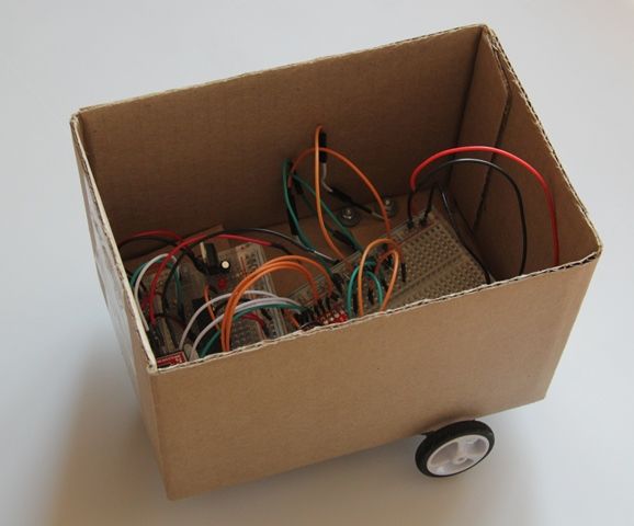
1 x Corrugated Card Box for a simple body
Step 2: Solder Connections
Solder the header pins onto the TB6612FNG
Solder pins onto the battery holder, to allow it to connect to the breadboard. This battery holder is for the motor power (we need to keep the power for the motors separate from the power that runs the Arduino)
Solder jumper cables onto the motors
Step 3: Prepare your Breadboard
The motor driver is on a separate half-size breadboard, so that it can stack above the Arduino on a Board. You could run this off the same board as the Arduino, if you used a full-size board.
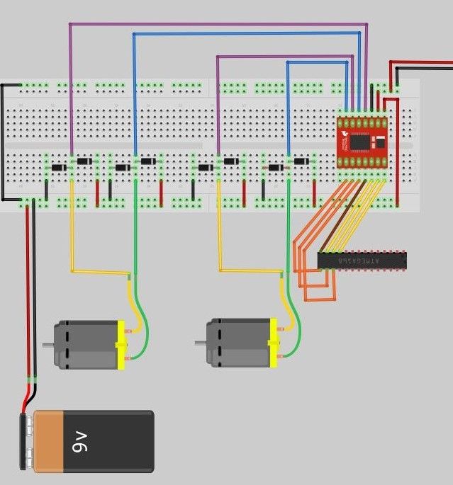
Power Layout:
I’m using one power rail on the breadboard to power my motors, and the other power rail to carry the 5V regulated power from the Arduino on a board. We need to connect the GND from both sources so that we’re working off a common GND – but never the positive supplies!
Place your Motor Driver at one end of the board, giving you space on the rest of the board to place the diodes and other connections.
Connect Arduino Power to your Motor Driver board. Connect the 5V from the Arduino on a Board to the VCC on the motor driver, and the GND to the GND. Make sure you are connecting these to the power rail that doesn’t provide power to the motors.
Step 4: Connect the Motor Control Pins
The motor driver switches the polarity on the 01 and 02 pairs for motor A and B to control the direction each motor spins. PWM pulses through the same connectors control the speed of each of the motors.
Connect the A01/A02 & B01/B02 from the motor drive to points on the breadboard. Space the jumper wires 2 points apart to allow us to connect the diodes in the next step, as well as to keep it compact.
Step 5: Connect the Motors to the Board
Connect the motor power rail (6V separate source) of the breadboard to the motor driver VM pin.
Back EMF Protection
In order to protect the driver and circuit against back EMF, we need to connect 2 rectifier diodes to each connection that the motors make to the breadboard. This setup provides Back EMF protection regardless of the direction the motor may spin.
One diode connects the motor terminal to Positive, the other diode connects the motor terminal to GND. It’s important to get the polarity right, so connect as follows:
– Motor Terminal —> Positive: white stripe of diode to the positive power rail
– Motor Terminal —> Ground: white strip of diode to the motor terminal
Then, connect the motor to the breadboard.
Repeat this for each of the 3 remaining motor outputs
Motor Power Source
Finally, connect the Motor Power connector to the Motor power rail
Step 6: Connect the Control Pins
We’ll now connect the pins on the Arduino that tell the motor driver what to do.
As we’re connecting the Arduino on a Board that we built (and not an Uno etc.), you need to remember that the pin numbers on the ATmega below are the logical, not physical ones. To remind you, I’ve included the logical pin numbers in a diagram above, the ones in blue square parentheses (eg. logical pin 4 = physical pin 6).
Connect as follows:
– ATmega Pin 5 –> PWMA (Speed for motor A)
– ATmega Pin 6 –> AIN1 (Direction #1 for Motor A)
– ATmega Pin 7 –> AIN2 (Direction #2 for Motor A)
– ATmega pin 8 –> STBY (Disconnect / Connect Motors)
– ATmega Pin 9 –> PWMB (Speed for motor B)
– ATmega Pin 10 –> BIN2 (Direction #2 for Motor A)
– ATmega Pin 11 –> BIN1 (Direction #1 for Motor B)
For more detail: BaW-Bot Part 2: Build the motor-controller & body