A quick rundown of how the system will operate is as follows:
The accelerometer constantly looks to see if the user is in motion. While the user is at rest, the unit takes a GPS and temperature reading every 15 minutes. When motion is detected the GPS unit is turned on. After 2-minutes passes the GPS unit and thermometer again take samples. If motion was detected during that two minute period the 2-minute wait and sample period repeats until the user is at rest again. This is done in order to conserve energy.
All the GPS and temperature data is stored on the SD card. Upon pushing the button on the front of the unit, all data is off-loaded (requires a USB connection to a laptop) and sent to a back end server system for analysis. The backend algorithm (coded in Java) extracts the useful features from the data (such as GPS error, # satellites and temperature) to build a decision tree that classifies the location as indoor or outdoor. The algorithm also utilizes the assistance of online public weather API’s as well a GIS web service which tells if lat/long points are within a building or not, to produce a report for the user. The report shows the amount of time (discrete periods of the day) ,and location history along with whether the user was inside or outside.
The arduino code, backend algorithm code as well as the GIS server can be found at https://github.com/pretsb/838fproject
This requires the following equipment:
Arduino Uno
Arduino WiFi Shield
GPS Unit (LS20031)
BMP085 Thermometer/Barometer
ADXL335 Accelerometer
Button
LED Light
2.2K Ohm resister
9V Battery pack
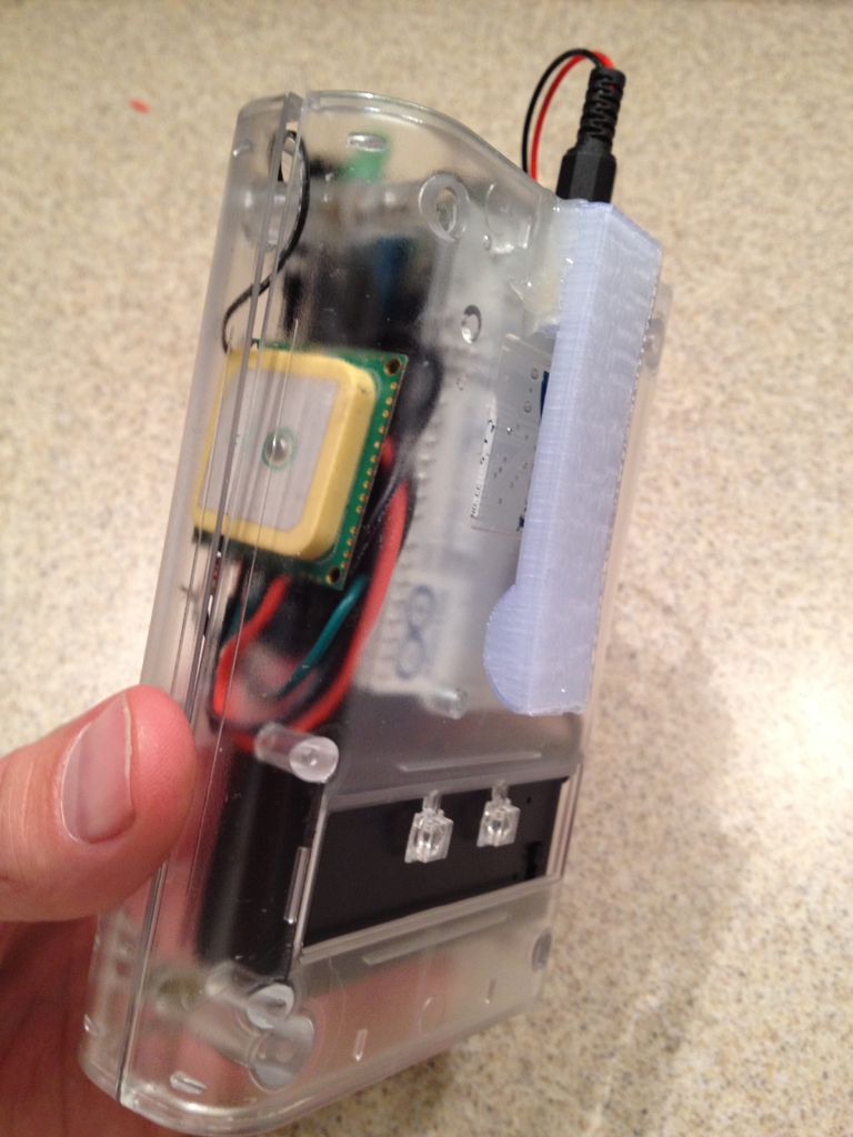
Adafruit Arduino Case
Various wires..
This instructable was made as part of the final project requirement in the
CS graduate course “Tangible Interactive Computing” at the University of
Maryland, College Park taught by Professor Jon Froehlich. The course
focused on exploring the materiality of interactive computing and, in the
words of Hiroshii Ishii, sought to “seamlessly couple the dual worlds of
bits and atoms.” Please see http://cmsc838f-f12.wikispaces.com/ for more
details.
A video tour of the project as well as a quick overview can be seen here:
 Remove these ads by Signing Up
Step 1: Add Arduino Uno to the shell
The shell has a nice few screw hole designed to hold the Arduino. We’ll screw the Uno itself to the shell using the enclosed screws and move on….
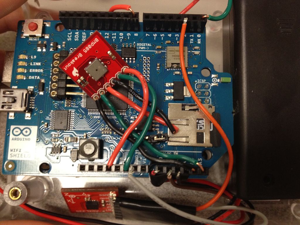
Step 2: Install WiFi Shield and SD Card
Failing to recognize these pin-outs will cause either the shield or your external peripheral to stop working.
We’ll simply slip the shield onto the Uno and slip the SD micro card into the shield itself and continue….
Step 3: Solder wire to the Barometer/Thermometer
I
chose to solder wire to the pin-outs, as shown, to allow more flexibility in the placement of the device. Leads would add to the inflexible size of the device as wires allow me to bend them as needed all the way down to the breakout board.We will explore wiring later in the project, for now we simply just solder the 6 – 3″ wires to the breakout board and trim them later as needed.
Step 4: Solder wires to the GPS Unit
We will not use the TinyGPS library due to memory constraints and thus only read data off of the GPS unit through its serial connection. A good tutorial on how to use the GPS unit can be found here: http://store.makerbot.com/replicator.html
The colored wires (from left to right) are to be connected as follows:
Orange – 3.3V (the GPS can handle 5V as well if needed).
Green – Signal / Serial TX
Black – Grnd
We chose digital 8 to power the device as it gives us the ability to switch the unit on and off as it draws quite a bit of power. We will use the accelerometer to dictate when we need to gather a GPS signal. Thus simple ‘digitalWrite(8, HIGH)’ and ‘digitalWrite(8, LOW)’ commands will allow us to easily switch on and off the unit.
We tape the back of the GPS unit to prevent shorting from taking place in the event a bare wire makes contact with the Unit. This also protects the back of the unit as it will later be packed tight into the shell.
Step 5: Solder leads to accelerometer
Step 6: Prepare the accelerometer
We then plug each end into the leads of the accelerometer in an alternating pattern as show in the picture. We’ll conclude the connection by wrapping the connections in electrical tape.
Our connection scheme will be as follows:
VCC – 3.3V ONLY! Don’t fry the device 🙂
GND – common ground. We will place this in the ground pin just below the 5V (we will use the other ground for the barometer/thermometer later)
X – Analog 0
Y – Analog 1
Z – Analog 2
Step 7: Connect GPS Unit
One thing to note about the GPS unit with this connection: The RX/TX connection pins replaces the serial communication of the USB serial cable once this unit is powered up and running. Thus, if the GPS unit were cabled up to the 3.3V or 5V connection vs. the digital pin you would not be able to upload code to the Uno as the GPS unit would be using the Serial. One should use a similar wiring approach when testing the GPS unit to allow for code uploading. Otherwise you will need to disconnect either the power or serial wire each time you need to upload code.