It’s amazing what you can accomplish with LEDs!
How the project works:
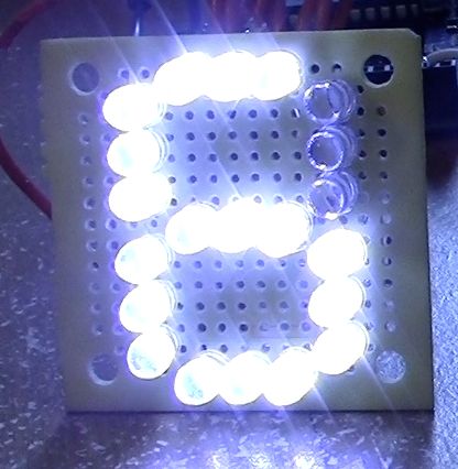
All the anodes of one row are connected together. There are 3 LEDs in one row. See picture. When you supply voltage to the row, the whole row lights up.
So, connecting all the cathodes together, I used Arduino to program each row to turn on and off. In the picture above, here are the rows that Arduino is turning on: Row 1, 2, 4, 5, 6, 7,
Remember, the way instrucables is set up, the pictures come first, then the explanation.
If you are interested in making this project, please read over this whole instrucable BEFORE you start and get confused! And, please, don’t forget too look at ALL the pictures and the boxes for them.
Here is a video of my the display using numbers. The next is it displaying the word, ALPHA.
1. What did you make?
The idea started when I was getting frustrated because I couldn’t get my 7 segment display to work with one of my ICs, so I decided upon making my own, so that I’d could control it in basically any way I wanted, including simple text.
2. How did you make it?
The very first thing I did was get out my sketchbook and draw down my ideas, and how I would connect them together.
I started working on this project at 11:30 pm, and kept on going until about 4:30 A.M.. I kept on running into obstacles, such accidentally soldering the negative and positive leads of 3 LEDs together! I made it with 27 LEDs, a small piece of perf board, some basic tools, wires, and most importantly my newly-bought Arduino. I did this project by myself.
3. Where did you make it?
Well. . . I made this project all in my room, on my makeshift desk,and downstairs in our office (for programming Arduino). The more I programmed, the more problems arose, so I had to keep on running back and forth between my soldering un upstairs and the computer down stairs! I wore a path through my carpet, down the creaking wooden stairs, across the tile, over the wooden floor in my office to the computer. How did the project connect to other activities in my life? I was able to count this for my schoolwork! I aslo used this project as a show-off to Bravo, (another group in my activities, I’m ALPHA)
4. What did you learn?
- Where do I start? I learned that I should have used a resistor for each LED, instead of one resistor
- The BIGGEST thing I learned was how to program my Arduino!
- I learned some more techniques about soldering
- I also learned a little bit more about LEDs themselves
If I could do anything differently i would have bought 27 resistors and soldered them to each LED!
What am I proudest of? My success! I would have never thought it woud be such an interest with my friends!
 Remove these ads by Signing Up
Step 1: Ingredients:
TOOLS:
1x Wire strippers & snipers
1x Solder
1x Soldering pencil
1x Wire strippers & snipers
1x Needle-nose pliers
1x Solder
1x Soldering pencil
You may need some wire cutters other than the ones on the stripper. See step 5.
Something to cut perf board
PARTS:
1x Perf Board (http://www.radioshack.com/product/index.jsp?productId=2104052)
1x Smaller strip of perf (not necessary, but recommended)
ELECTRONICS:
21x White (or other color) LEDs
1x 50k pot (potentiometer)
1x Arduino & USB cable & power (optional)
Various jumper wires, MAX, 9
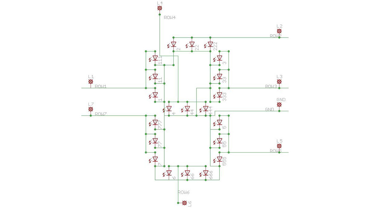
Step 2: Getting Familiar With The Design
Step 3: Prepping the Perf Board
[1/21/13 UPDATE]
I added some photos of how the LEDs fit. The first picture is of them vertically, and the second is of them sideways(horizontally).