1 Instructions
This is a group assignment for you to work on during class. You only need to hand in one copy of this, but make sure that the names of all of your group members are on this sheet to receive credit. Complete all of the sections below during class and make sure to get the instructor or TA to sign off where required. You may want to keep your own notes on what you complete since parts of the next homework will build on this lab. In this lab you will learn to connect and wire basic components on a breadboard. You will interface with a button and a RGB LED and will explore how long it takes to perform various operations on different integer types. Before starting this lab, make sure you are familiar with the layout of the breadboard and how each location is connected to each other. If you are unsure ask the instructor before you break something!
2 Resistors
In this lab you will be using 100, 180, and 47,000 (47k) ohm resistors. These are identified by different color stripes on them. You can refer to: http://en.wikipedia.org/wiki/Electronic_color_code to figure out the color coding scheme, but for your reference the 100 ohm resistor has the color code brown-black-brown-yellow, the 180 ohm is brown-gray(blueish)-brown-yellow, and the 47k is yellow-violet-orange-yellow. You should have three 100 ohm, three 180 ohm, and two 47k resistors in your packet.
3 LEDs
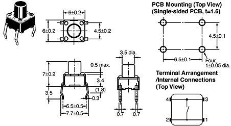
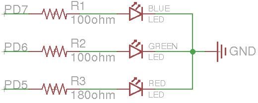
For this seciton, you will be using a tri-color RGB LED. On the breadboard, implement the circuit defined by the schematic in Figure 1, but do not connect it to the Arduino yet. You should refer to Figure 2 to determine the pin-to-color mapping of the LED. Checkoff: Once you have completed wiring on the breadboard, have the instructor verify the connections before moving onto the next section.
Now connect the circuit on your breadboard to the proper pins on your Arduino. The pins (PD5, PD6, PD7) are given in terms of the pin names on the Atmel, you will need to determine the correct correspondence to the output pins on the Arduino itself by refering to the Arduino schematic. Write the code1 for your Arduino to turn on and off each of these LEDs2. Does the LED turn on when the output pin is high or low? For ease of use, you may want to define variable or macros that lets you turn on/off a particular color LED by name instead of pin number. Checkoff: Write code that continually cycles through the pattern R,RG,G,GB,B,RB,ALL_OFF where RG means the red and green LED should be on at the same time. Show your completed program to an instructor for checkoff. I suggest that you put all of the code for this question in single function that you continually call from the loop function. That way you can easily comment it out when you work on the next part of this lab, without having to delete any code.
For more detail: CSCE 236 Embedded Systems