Stepper motors are not smooth – they move in “steps”. Different motors have a different number of steps to make one complete rotation. You use software to step the motor forward or backward at different speeds. There are two kinds of stepper motor bipolar and unipolar – Unipolar will have five or six cables coming from them. Bipolar will always have four. They function the same but you need different chips to drive them.
Unipolar Stepper motors
- 5 – 6 wires
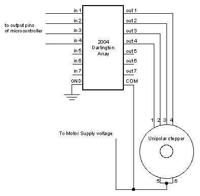
- require the Darlington Array IC chip.
- not very common
- easy to wire
Bipolar Stepper motors
- 4 wires
- require the dual H-Bridge IC chip – L293D.
- Much more common
- trickier to wire (but still pretty easy)
How to tell if you have a stepper motor? Are there 4 or more wires coming out of it? When you turn it in your fingers can you feel it “step”? Steppers are in a lot of printers and scanners, so we’ll be sure to see them “in the wild” next week. here’s a nice page about stepper motors
On a 6 wire stepper two of these lines will be power. Start by picking any two wires and measure the resistance across the wire.
- plug the black tester lead into the COM port and the red lead into the V port to the right of the COM port.
- put the meter on the ohm setting. (see image).
- take the protective tips off the testers – d’uh.
- if there is no resistance at all the wires are on opposite “sides” of the motor.
- if there is low resistance then one of the wires is the power.
- if there is high resistance then neither wire is the power, but they do have a common power (on the same “side”).
- how do you know if the resistance is high or low? Compare them! Each type of motor will give you different readings – it the relationship between the resistance that’s the key.
But which wire is which, because it matters that we turn them on and off in the right sequence.
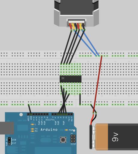
- using the breadboard and the Arduino plug the 2 common power wires into the 5 volt.
- pick (at random) one of the wires and plug it into ground. This will be wire 4 when we are done, but for now it goes in ground just to run this test. I DOES NOT matter which wire you choose to be wire 4, it’s the relationship between wires that’s important.
- take another wire and plug it into ground also, but watch the motor as you do it (it may help to put a piece of tape on the motor)
- If the shaft does not move, you have Coil 2.
- If the shaft jogs (slightly)clockwise, you have Coil 3.
- If the shaft jogs (slightly) counter-clockwise, you have Coil 1.
I had always done this step by trial and error, which works too but takes forever. Thanks to this nice site for the time saving tip.
In the gif we are testing the yellow wire to see what pin it goes to by watching how the motor “jogs” when we plug it into ground.
In some respects the bipolar motor is easier because it has fewer wires, but there’s no shortcut I know for figuring out which is which. Still Trial and error takes a lot less time. The wiring is actually pretty straight forward. Although you can run a stepper off of a the 5 volts on Arduino it good practice to have it use it’s own power supply.
For more detail: Stepper Motors