Our final project for ECE 4760 provides a simple but effective exercise monitoring system of the user’s walk or run. With an increase of the number of health conscious individuals hoping to remain fit, we designed a system that allows the user to keep track of his or her total number steps, current speed, and total distance in both real time and with a data logging system. This is especially useful for any students who are concerned with how much exercise they are getting by simply going to class!
Using the ATmega644 microcontroller, we perform the necessary communications between the accelerometer which obtains the data, the LCD screen which displays real time data, and the SD card which stores the data. The logged data on the SD card can then be inserted into a user PC with MATLAB to plot the relevant exercise waveforms.
Although the short 5-week project is still very clearly in prototyping stage, it provides the groundwork and proof of concept for reasonably accurate distance and speed calculations using two simple accelerometers.
System Level Design
Rationale | Background Math | Logical Structure | Hardware/Software Tradeoffs | Applicable Standards | Existing Patents Copyrights and Trademarks
Rationale
Our project inspiration came from a previous project both of us had worked on a previous year. At that time, we had both worked on separate projects involving a simple Pedometer using a MSP430 microcontroller. Unfortunately, due to time constraints and hardware failures, we were unable to complete the project. Unwilling to accept defeat, we attempted the project again, but with the intention of providing greater functionality, better user interface, and a working final product. While we understood that many smartphone apps provide a similar functionality, we wanted to see if we could provide comparable functionality without all the need for fancy hardware and expensive data plan.
From the beginning, we decided to use the ADXL345 digital 3-axis accelerometer, not only because of its expansive functionality and zero cost (due to borrowing the part), but also because we had extensive familiarity with the part which would reduce the start-up design time. Initially we had planned on using the built in interrupts and threshold functionality found on the ADXL345, but after determining that we would be using the Tiny Real Time (hereafter called TRT) multitasking kernel, we found that it was easier to poll the accelerometer for data.
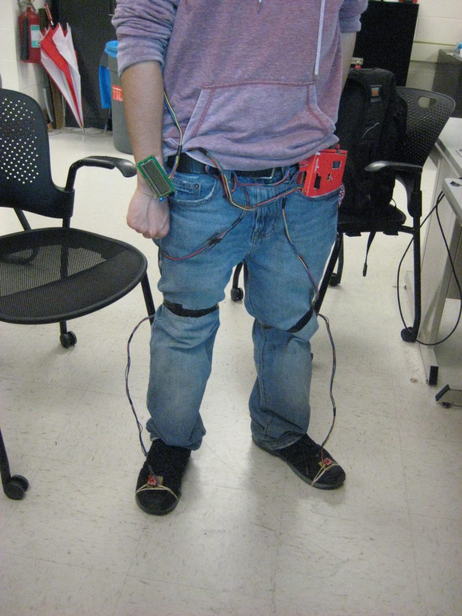
Apart from data acquisition, our exercise measurement system provides two forms of data display and analysis. The more simple of the two involves a simple 16×2 character LCD screen. It provides all the necessary information to the user while the user is walking or running. This includes the number of steps taken, average speed, and total distance using the dead reckoning navigation technique. While we had hoped to improve upon our distance and velocity calculations using a GPS system as a potential improvement, we decided against the addition due to both limited time and the inability to use GPS indoors, where many potential walkers would be using the device.
Finally, our secondary data display and analysis device involves using the common SD card to log user data and plot them on MATLAB. This provides more than simply the above mentioned metrics displayed on the LCD but also the raw acceleration data before much of the noise canceling is performed. This allows for the more in-depth and curious user to look at the slight differences in walking style which may be found in persons suffering from anything ranging from a sprained ankle to more serious medical conditions. As a plus, the user can keep a record of all of his or her exercises to track changes over time.
Background Math
This project does not have conceptually difficult math. There are two main calculations that are taking place: detecting a step and determining distance. We tried a couple different methods of calculations, which can be read in Appendix B, but we want to focus on what’s working in our final code.
When we break down what constitutes a step, we can focus on a single, critical event: the cessation of a foot’s downward motion due to collision with some surface. From mechanics, we know that any change in an object’s momentum is either due to an impulse from this collision. We can then say the following is valid:
Furthermore, we know that the force applied looks like a spike. This external force is directly proportional to acceleration, per Newton’s Second Law. Now, the implication of this is clear – by placing an accelerometer on each foot, we should be able to record these spikes directly from acceleration data and correlate them to a step.
To determine what a step is, we use a dynamic envelope threshold based on a running average of the acceleration data and call a step a point at which the acceleration exceeds this threshold. By implementing this, we can accomplish a few things – we reasonably assume that the spike will exceed the running average by a decent margin and we allow the threshold to change, which allows for sensing softer steps and prevents from overcounting steps. Even then, there will be instances when the acceleration spikes above the threshold due to noise and could be counted as a step in error.
To prevent this double counting, we add a simple timer. Depending on the pace someone takes, we can expect a minimum amount of time to pass between steps – logically, the faster someone runs, the quicker we can expect these steps. Arbitrarily, we impose two different values for this minimum time delay, 400 ms at a walking pace and 200 ms for a brisk pace and running. To determine which value to use when, we apply a bit more physics.
A logical assumption that can be verified is that as a person speeds up their pace, their foot will be travelling down with a greater velocity before stopping, which means a larger spike over a quicker time. If we take the acceleration and take the differentials to find the jerk, we will observe that the over time, a faster pace has a distinctly larger moving average of jerk. We set compare this average jerk to an arbitrary threshold to determine whether a larger or smaller delay is to be used.
Our method of determining distance is dependent on having accurate step data. Assuming we have accurate steps, we can use two parameters to determine a rough speed – pace or the rate of stepping, and the step length. Quite simply, the rough velocity will be the pace multiplied by the step length. This makes intuitive sense – if I take 4 steps a second and each step is about a half a foot, one can expect to travel 2 feet in a second. We now have a measure of speed, and we can easily integrate to find a distance.
For both essential components, there is a considerable amount of arbitrary values that are set – number of samples to use for the running average, different thresholds, the strides, etc. Almost all of these are derived from running numerous iterations of the code, tweaking parameters and attempting to see what worked best.
Logical Structure
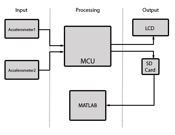
The structure of this design centers around the ATmega644 and its three peripherals, namely the accelerometer, LCD screen, and SD card reader with MATLAB plotting. The peripherals can be divided into two broad categories of function: data input, and data output. As can be deduced, the accelerometer system was used for data acquisition, and the LCD screen and SD card were used to log or present data that would be meaningful for the user in real time or for future use.
Upon startup of the program, operation of the system proceeds as follows:
- User positions body in normal walking orientation
- User presses a button to initialize accelerometer calibration and waits a few seconds
- User proceeds about normal activities while logging data
- User presses the button again to stop logging data and close log file
***optional***
- User may load SD card into PC running MATLAB
- User loads MATLAB and changes the working directory to the SD card
- User runs the MATLAB script
Hardware/Software Tradeoffs
The hardware logical design is straightforward, consisting of the main microcontroller communicating with its 3 peripherals (LCD, accelerometers, SD card). Since none of these peripherals are extremely expensive or computation heavy, the main difficulty lay in software tradeoffs. Since the entire program was run using the TRT scheduler, how much time before the next release and deadline for each task was important in determining the tradeoffs between user experience and total data logged.
Since the both the accelerometers and SD card run on the SPI bus, their rate depended solely on the SPI clock speed. This determined how quickly a single byte of data was transmitted across the SPI bus from master (MCU) to slave (peripherals) and back. The sclk is run at 4MHz because a clock divider of 4 was used on the MCU which was also less than 5MHz, the maximum clock speed on the ADXL345. 4 MHz is twice the minimum required speed to run the accelerometer at 3200Hz maximum output rate. Since human walking applications do not require the accelerometer to acquire new data so quickly, the default output rate of 100Hz is more than enough.
The rate at which the MCU reads the SPI bus for new data is actually the rate at which data is received from the accelerometer and this rate heavily depends on the load of the scheduler and whether other processes have passed or missed its deadlines. The sample data function currently averages over 4 data points, which reads the registers from the accelerometer at rate 800Hz. The greater this sampling rate, the finer the logged data. At a high enough sampling rate however, the LCD interface needs to display slower and will affect the user experience because of slow refresh rates.
The SD card also operates on the same SPI bus as the accelerometer and writes to the SD card at the same sclock speed. However, during the disk initialize protocol, the SPI clock must be reduced to a lower speed as it writes 0xFF to the SPI buffer to initialize. If the clock speed is too fast, not enough time may be given to the sclock to clear the buffer and properly initialize the disk.
Applicable Standards
Our design does not have a lot of interactions with the typical standards. This iteration of the project is wired, so we don’t have to worry about any wireless or radio communication standards that other projects cite. For software, the ANSI C protocol is already met through the use of the GCC compiler in class and the implemented FATFS protocol developed by ChaN. We use the SPI protocol developed by Motorola throughout the project – as the Mega644 MCU, ADXL345 accelerometer, and SD card already comply with SPI protocol, there’s little we can do to violate this protocol and have an operational project. While we didn’t need to do anything concerning the actual concerning the SD card hardware, the cards complied with the Secure Digital formatting standard.
Searching through IEEE standards and ISO returns one active project that could possibly be a standard we need to consider: P11073-10441 – IEEE Draft Standard for Health Informatics – Personal Health Device Communication – Part 10441: Device Specialization – Cardiovascular Fitness and Activity Monitor. At the moment, it’s only an active project, not a standard, and we don’t have information as to what the specific standard entails. However, if this is published and becomes a standard, we would need to see if our device is included. We don’t directly measure any biometrics, but our designed application is in essence an activity monitor, so we need to be careful with this standard. Simultaneously, the description of the standard in development could render our above concern moot – the standard speaks to defining a normative means of communication between devices and what they define as managers (cell phones, computers, etc.) Our current design does not directly interact with other devices and instead relies on a more primitive “store data and look at it later”. So again, while we will probably monitor this standard for the sake of remaining in good standing, it’s doubtful that standard will even be applicable.
Existing Patents Copyrights and Trademarks
We’re certain that a patent on the concept of the pedometer exists in some form, and there are probably many that interface stepping with distance calculations.
One paper in particular that is of great relevance in terms of copyright is an article written for Analog Dialogue, which is a magazine from Analog Devices.
At the time we found this article, we had already found a relatively accurate way of determining a step and we were writing code to improve the accuracy for different speeds. This article presents an alternate method of deriving the occurrence of a step, but discusses the approximate speeds related to the calculated paces.
So our concept is not exactly novel. However, we’ll talk with Bruce – as far as we could see, few people used two accelerometers on the feet or used a running average threshold. Of course, our rationale is that this would be the foundation of a much larger sensor network, whereas other projects just want a simple pedometer.
We use SD and microSD cards, which already have patents on them. If we wanted to pursue patents, we need to look into how patented products are implemented and how royalty fees check out.
Hardware Design
Mega644 Board | Voltage Regulator | ADXL345 | SD Card Reader | Voltage Level Considerations | LCD | Button Setup | Overall SetupThis section will breakdown the hardware components of our project and discuss any details and decisions made. Datasheets will be referenced often, and the appendices will contain links to the relevant components. When possible, we will provide commentary on the usage of particular parts and insights for future projects.
Our schematics can be found for download in Appendix D
Mega644 Board
We used a ATmega644 board mounted on a custom-made circuit board designed by Bruce Land. The circuit board provides some key functionality to the project. For the end result, we have access to pins for SPI communication, which is important for the functioning of our project. There’s a voltage regulator to switch a 9V supply down to 5V for MCU operation, which allows us to use either power supply from the lab or a 9V battery. There’s also the serial communications port which we used extensively for debugging purposes. The final implementation does not need the serial comm port to function properly, though.
By the end of the project, hardware issues came up with the programmer, which uses pins B5, B6, and B7. After blowing one Mega644, we had taken precautions to program only when peripherals were removed and run the pogram without the AVR programmer attached. Nevertheless, we discovered an issue related to the programmer pins with the help of David Ackerman and Jon Amazon. We ended up having to solder a quick header to pull pins up to 5V Vcc. These are simply 10k resistors that tie MOSI, SCLK, and MISO to Vcc.
Voltage Regulator
Our project revolves around the implementation of different peripherals and being able to communicate with them. From the very beginning of our project, the need for a voltage regulator was obvious. The ADXL345 accelerometers and the SD and microSD cards are rated to operate with 2.7-3.6 V supply, while the Mega644 and the LCD’s use 5V supply. For this, we used the LP2951 voltage regulators found in lab.
We found Texas Instruments’ datasheet related to the LP2951 to be extremely helpful and clear about the design and application of the regulator. From this datasheet, we were able to program the regulator to output 3.3 V with constant 5V supply. This was a simple circuit, with a resistive divider from the output voltage to the LP2951’s feedback port. This sets the input to the regulator’s error amplifier equal, which drives it according to the equation (from TI)
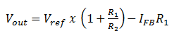
where Ifb was rated as typically being 20nA.
For 3.3 V, we set R2 to 10k and R1 to a nominal 16.7 k (created using a 5.2k, 1k, and 10k in series).
We included input and output capacitors early on to help with loop stability. In the final setup, the power supplied by the Mega644 was not AC, so we didn’t need to use the 1uF input capacitor. Additionally, the load current out of the LP2951 is far below the worst case condition of 100 mA, so the 2.2uF output capacitor is also overkill. However, at the time we built the regulator circuit, we were still adding peripherals and wanted to be safe with drawing too much current.
After discussion with other project groups, we found that the schematic suggested by Texas Instrument was very robust and eschewed regulator problems that previous projects had encountered. We would recommend that any group shifting voltage level read the TI datasheet. The output voltage can be programmed at any level between the internal 1.235V and 30V, but other circuits might require more than just the resistive divider and capacitors.
ADXL345
Our project revolves around the use of the ADXL345 triple axis accelerometer mounted on a breakout board. The breakout board has the pins neatly arranged on one side. From top to bottom, the pins are (as seen above), GND, VCC, CS, INT1, INT2, SDO, SDA, SCL. We didn’t use the INT1 or INT2 pins in our project, so they remain unsoldered to headers. Because the accelerometers were borrowed, we used a small 2″ solder board to build a dock for the accelerometers. The accelerometers can easily be interchanged then as the chips work.
The accelerometers are three axis accelerometers, with a range of +/- 16g at 3.9mg/LSB max resolution. Earlier on, we had been expecting to use at least two of the axes. As of our demo set up, we actually only use 1 accelerometer, so this code could be revised and reworked for 1-axis accelerometers.
SD Card Reader
To log data, we decided to use an SD card to log accelerometer data whenever polling and calculations were finished. We chose this option for a couple reasons:
- Due to the plethora of applications SD and microSD cards have, any user would reasonably have a card around that can be used for this project.
- The price of SD sockets and microSD adaptors is much cheaper than a receiver/transmitter module.
The card sockets are just metal connectors from the solder board to the card’s pins, and can easily be implemented with headers.
For the card themselves, we used a standard SanDisk 2GB SD card and (later on) a 4GB microSD card, which can be easily found and purchased commercially. Some projects used the SD cards with 5 V power, but we use 3.3V, as this is a safe operating range according to SanDisk.
For the purpose of our project, we needed to know the SPI pins that were available. both the microSD and SD cards have the same configuration as seen above, and as such, are interchangeable given the proper sockets.
From left to right, the 9 pins are:
N.C.; MISO; Ground; SCLK; VCC; Ground; MOSI; CS; N.C.
Probably the only consideration that needs to made for the SD card reader is the structural integrity of the socket. Earlier on in the project, we had sampled SD card sockets from Molex which were simply metal cages with header pins. Because the location of the pins, the card was balanced precariously over header pins while being soldered to the board. There was no real support behind or underneath the card, which eventually led to the header pins ripping out once.
The microSD socket we used in the end is not much better. The socket is just a microSD to SD adaptor that has the pins soldered to header pins. There’s no structural support, and one concern is that this is the least robust part of our hardware.
For more detail: Simple and reasonably accurate pedometer system