In the past five weeks, we have considered and built three projects, ranging from: optical sensing, electromyography (EMG), and galvanic skin response detection. Initially, our project was using an optical sensor and EMG to detect finger movement for applications, such as: playing piano and Morse code. However, after completing the hardware, due to issues with the hardware we could no longer measure a valid signal. We switched directions and built a stress sensing computer mouse utilizing galvanic skin response and heart rate. Our goal is to use this device to measure changes in the autonomic nervous system. The device vibrates to the user’s heartbeat, increasing the user’s awareness of his/her stress level. In order to test and prove the functionality of the device, we pair this hardware with a game tuned to increase the user’s stress level by increasing the speed of a 1-D maze Falldown-style game.
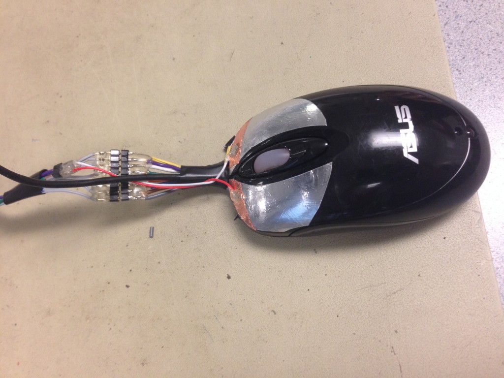
The final product.
High Level Design top
Rationale and Source of Project Idea
Stress is a physiological and biological response to a stressors such as environmental condition or stimulus. As our body encountered a difficult situation, our body prepared itself with focus, strength and heightened alertness. Our nervous system responds to a threat by releasing a flood of stress hormones, including adrenaline and cortisol. These hormones rouse the body for emergency action. The Galvanic Skin Response (GSR) corresponds to the surface resistance of the user’s skin. At high levels of stress, the sweat glands in the hands increase activity, increasing the salt and moisture content of the skin thus reducing surface resistance.
For this objective, we have designed a biometric sensing computer mouse that takes into consideration heart rate and galvanic skin response in order to detect the different conductance of the skin when a person is under stress or when not. In order to stimulate stress, we invite the user to play the Falldown game. As the user is getting closer to the end of the game, his/her stress level is expected to increase, the ball will start to move faster and the game stimulates the user to increase his/her concentration on the game.
Logical Structure
High-level block diagram.
Relationship of Design to Available Standards
Based on FDA Regulation, this device is considered as Class II Medical Device. The most important FDA Standards that need to be considered is the electrical safety. Since our device is line-powered, it is important for us to describe the design features that assure the patient will be isolated from AC line voltage under any condition of electrical component failure. We will also take into consideration the effect of any line-powered accessories that connect to the device, and the use of a line-powered battery charger if the device is powered by a low voltage battery. In order to prevent the heat produced by the electrical energy to cause injury to the subject’s skin, the average current density should not exceed 0.25 Watts per square centimeter. In addition, the device needs to satisfy other industrial standards, specifically UL 544 or any other electrical safety standard.
Existing Patents
There are several patents that discuss a galvanic skin response. For instance, US6415176B1 mentioned a skin-conducting sensor as a wearable device, specifically gloves. The device includes an on-board power source and a source of illumination that provides a continuous visual indication of skin conductivity. While in US3870034, the configuration of the device is a strap. The device is like a wristwatch which houses an oscillator circuit, a battery, a sound emitting device and a pair of spaced electrodes located on the opposite ends of the casing so that the wearer may conveniently touch the two electrodes with two fingers.
Past Designs: Optical Sensor and EMG for Gesture Control top
Hardware Design
Operational Description
The operating principle of the optical gesture recognition is to measure the changes in reflectance at multiple points along the wrist to detect changes in the underlying tissue structure of the wrist. Differential optical pairs measure optical reflectivity of IR (880nm) light at two points along the wrist. As the tendons shift position due to muscle contractions for the fingers, the differential optical reflectivity can be measured. These values are input as features to the machine learning classifier.
Figure 1 to 3 are the hardware designs of our optical sensor idea. Figure 1 shows the optical sensor circuit, which comprises of mainly INA121, 100k TrimPot, and BJT Transistors. The recorded signal was buffered, filtered (both actively and passively), and amplified with two gain stages (gain of 30 for each stage). For the first stage amplifier, we used an instrumentation amplifier INA121.
At the beginning, we soldered the IRs and Phototransistors on a electrical board and then used glue to stabilize the whole system in the configuration that will place nicely on the user’s wrist. However, after testing that setup, the obtained signals was not as good as we wanted; therefore, we decided to design a better housing for the IRs and Phototransistors. As the result, a hard housing as shown in Figure 2 was 3D printed. At the same time, we also designed a flexible housing which could wrap around user’s wrist. However, before we attempted to test out these configurations, the signal was no longer there. As a consequence, we decided to move on with our second design idea: using EMG signal to play a piano.
Figure 1. Optical Sensor Idea Hardware
Figure 2. IRs and Phototransistors Housing
Figure 3. Flexible IRs and Phototransistors Housing

Figure 4 shows the EMG circuit which was our second design idea. The wet electrodes are coupled to the circuit via two 1uF capacitors. By capacitively coupling the inputs, we eliminate any possibility of DC current flowing through the user while severely increasing the AC impedance, thus reducing possible AC current through the user, even though the circuit is electrically isolated from ground. The signal passes through a two-stage passive band-pass filter before the pre-amp. We used an instrumentation amplifier INA121 with gain of 22 as our first stage amplifier. Using its low input bias current (3fA) and high common-mode rejection (84dB), this initial amplification stage increased the SNR enough for further amplification. This signal then passes through an additional passive filtering stage before two non-inverting amplifiers. The final signal is high pass filtered and level shifted to around 1.5V, which allows it to pass effectively through the optical isolator. After having a good signal for one channel, we decided to duplicate that circuit for three more channels. However, after wiring 2 more circuits, the signal was no longer there. We attempted troubleshooting but we failed in receiving any valid signals after that. As a result, we moved on to our most recent idea: Biometric Sensing Computer Mouse.
For more detail: Biometric Sensing Computer Mouse