For our project, we built a planar, 2 degree-of-freedom haptic device for educational use. The design is based on a 5-bar mechanism. We wanted to build a device that would have the versatility to teach various concepts, but would still be relatively affordable (as the goal is implementation in classrooms). For this reason, we designed a device without a graphical display, that instead uses physical slides that can be changed by hand in order to demonstrate different haptic environments. The core learning objective of our device was to teach about potential fields, such as gravitational or electrical fields. However, it is important to note that the device is adaptable to virtually any planar task (such as navigating mazes or drawing mathematical functions). After building the device, a group of 50 high school students and several high school teachers tested it and responded positively as to its potential for classroom teaching.
Introduction
The objective was to create a device that would allow students to feel gravitational or electrical fields. Since this concept directly relates to force, it is a logical use of haptics. No sensory substitution or training is needed; the user directly experiences real forces. Additionally, gravitational forces naturally result in orbital motions which can be easily observed by the free motion of the end-effector. Williams et al. [1] discussed how haptic devices are especially well suited to the teaching of high school physics, owing to the importance of force in physical systems. He begins by noting that at the time of publication (2002), haptic systems for education were virtually non-existent. This study provides encouraging results for our proposed project, including student feedback, of which the overwhelming majority asserted that the experience was effective in accomplishing educational goals. Wies et al. [2] developed a device and environment for displaying electric fields, though they only used one charge with a uniform charge density sphere. This paper explicitly shows the utility of a haptic device in teaching a force-field type environment.
Background
Many 2-DOF devices have been built before, but predominately with different design criteria from out project. The first design option that we dismissed was a serial linkage. With a serial linkage, sequential links must carry the motor to actuate the next link, or a complicated cabling solution must be used. In our case, we desired to be able to give the system initial conditions and watch the resulting orbit of the end-effector. If the device was carrying large amounts of mass externally, then the inertia of these masses would cause the device motion to be largely governed by the device dynamics rather than the virtual dynamics. Additionally, we desired a system with symmetric linkages so that users would not be distracted by the asymmetry of the device when observing free motion of the end-effector. For this reason, we ruled out a design similar to the MIT Manus [3]. In their paper, Campion and Hayward [4] introduce a 2-DOF, direct drive device called a pantograph. This design is essentially a 5-bar mechanism with one bar grounded. Motors actuate two base bars, and the user places his or her fingers at the intersection of the free bars.
Methods
Mechanical Design and System Analysis
We began by adapting the design of the pantograph from Campion and Hayward [4].
Figure 1. Diagram of the pantograph, Campion, 2011.
The device developed in the paper is relatively small, having a workspace of about 60mm x 110 mm. For our application, we wanted users to be able to explore a workspace the size of a standard 8.5” x 11” sheet of paper (216mm x 279mm).
First, we used the inverse kinematics of the device to design a linkage capable of reaching the entire workspace. The grounded link is 10cm and the moving links are 25cm each. The linkage is shown at the four extremes.
Figure 2. Linkage at extremes of workspace.
Next, we evaluated the Jacobian at each point in the workspace to ensure the device is well conditioned. Our design has maximum condition number 3.4, which is relatively small, and is comparable to that from the original design in the literature.
Figure 3. Condition number of the Jacobian over the workspace.
Furthermore, to ensure a compelling haptic sensation, we wished to maximize the displayable forces at the end-effector. The workspace was discretized into 100 points. At each point, we determined the maximum force that could be displayed in 20 evenly spaced directions, based on the motor stall torque. We then took the smallest of these maximum directional forces at each point and plotted them over the workspace. Using only direct drive (no mechanical advantage) of Maxon RE25 motors, we obtained the following plot:
Figure 4. Maximum displayable force in an arbitrary direction over the workspace (direct drive).
For most of the workspace, the maximum displayable force that we could guarantee in an arbitrary direction was <0.4N, which was considered too small to be compelling. In light of this, we opted to drive the links with a capstan. Using the a capstan ratio of 11.15, we obtained the following maximum force plot:
Figure 5. Maximum displayable force in an arbitrary direction over the workspace (with capstan).
Here, the device is capable of displaying 3 to 4 N in an arbitrary direction over the entire workspace, which is considered more than sufficient for our purposes.
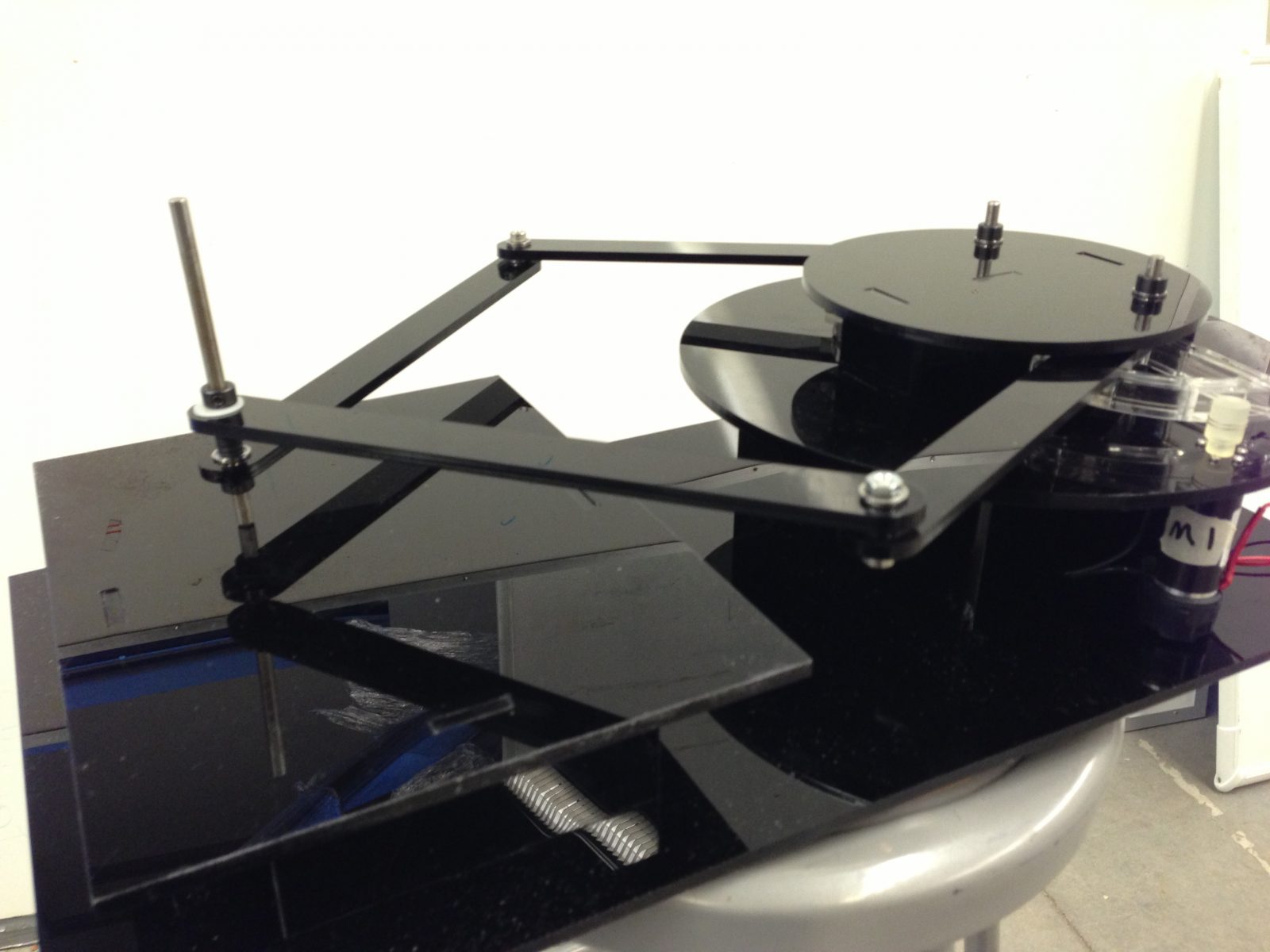
We fully modeled our design in SolidWorks. All links and base pieces are laser-cut acrylic, while the capstan pulley on the motor shaft is 3D printed (similar to ABS).
Figure 6. Isometric view of device.
The user holds the end-effector shaft, which moves over the flat surface. After construction, we decided that we needed to support the end-effector with a caster ball in order to prevent the links from bending while supporting the weight of a user’s hand.
Both links are driven with capstan drives, which were re-purposed from the haptic paddles. This is advantageous to those who may already be in possession of haptic paddles. If someone possesses a haptic paddle, he/she could create our device with only some acrylic and a few bearings.
Figure 7. Detail view of capstan.
Figure 8. Isometric View of the laser cut and assembled device.
Mechatronic Design and Control
We used an Arduino Uno for computation and control. From the haptics class, we also had an Ardumoto motor shield. However, we were concerned with overheating this board if running at stall torque on both of our motor simultaneously. For this reason, we ordered a Pololu Dual VNH5019 Motor Driver Shield. However, this motor shield was designed to use Pin 2 (one of only 2 interrupt pins) as a motor direction pin. We initially tried implementation with the default configuration, but quick motions of the motor shaft resulted in missing encoder ticks and a drift of our device position estimate, because one of the encoders was not wired with an interrupt pin. Because of this, we used the Pololu Motor Shield library to change the default pin assignment. Though this vacated pin 2 on the Arduino board for the encoders, we still had the problem that the motor shield was hardwired to accept its motor direction command on the second pin. For this reason, we did not directly stack the shield on the Arduino; we instead used a breadboard to route wires between the Arduino, the Pololu motor shield, and our Ardumoto board that was holding our encoder wiring. This allowed us to use whatever pins we wanted to drive the motor driver board rather than being forced to use corresponding pins on the motor driver board and the Arduino.
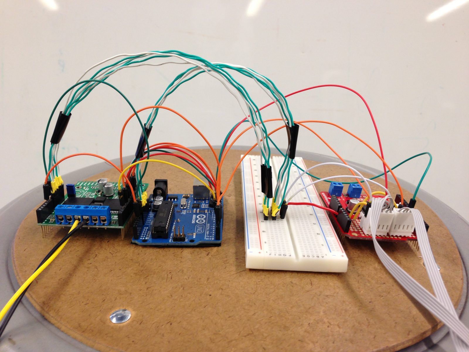
Figure 9. Pololu Motor Driver Shield, Arduino Uno, and Ardumoto board from left to right.
The Pololu Motor Driver Shield requires a motor command output between -400 and 400. Our code determines a needed force at the end-effector which is directly related to motor torque, and thus, motor current. Because this motor driver is voltage-commanded, our next step was to calibrate the voltage command to a to a current. We commanded several voltages, locked the motor shaft, and measured the current. The following plots show the result of the calibration.
For more detail: A Planar 2-DOF Haptic Device for Exploring Gravitational Fields