I am entering this project into the UP contest so if you think it is at all neat/delicious/gets you thinking then please give me a vote and help me, help you with more awesome projects =]
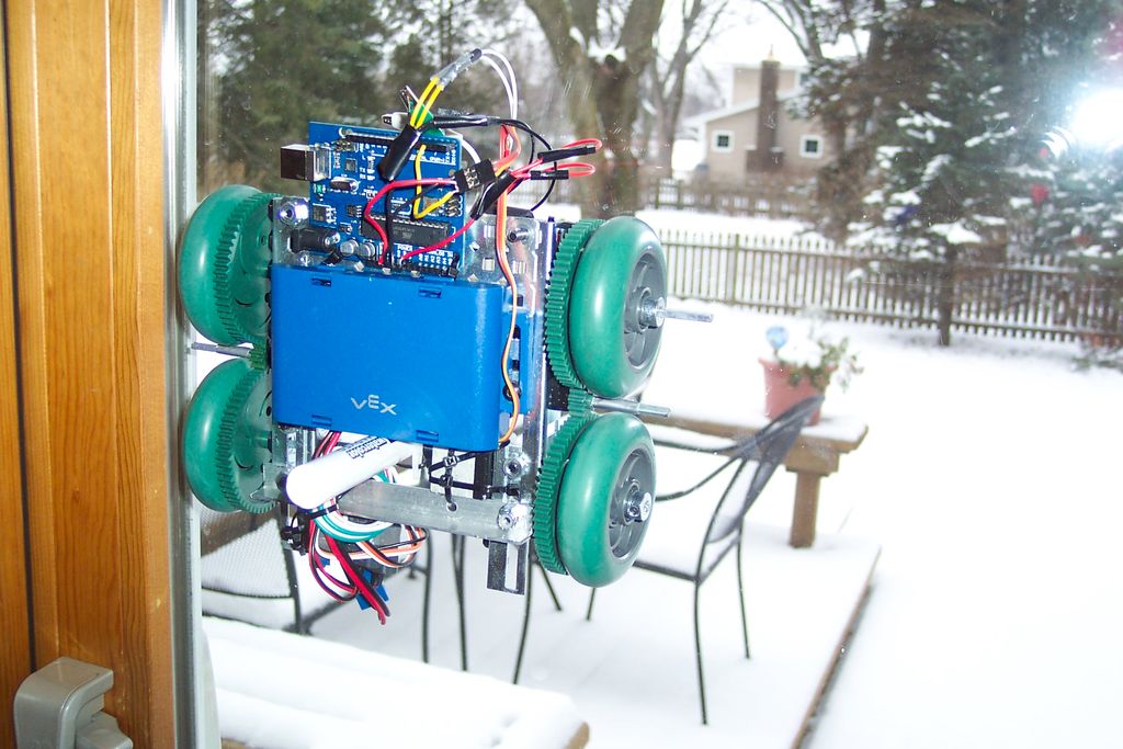
What I think is so enticing about this design is the wide applicability. It allows expression of ideas and creativity in normally unused spaces. The real challenge is what’s the biggest glass window can you find? This also has other applications as it could clean windows, or survey the sides of buildings, draw just on floors, etc.
The advantage of this design over a polargraph or other drawing method is that it is really easy to set up and draw on any size of window. Later in the ‘ible you will find the processing program I wrote for this, which takes input about your window size and robot specs and lets you to draw what you would like the robot to mark on your window; with a touch of a button it turns it into arduino code that fits in the arduino program I have supplied, so it can be easily uploaded to the robot. Then you just put the robot on the wall and watch it go to work! The autonomous nature of this design makes it free of wires while also not relying on any sort of wireless connection to do its work.
I did this project with scrap VEX metal and motors I had lying around, but don’t be discouraged if you don’t have those!!! It will work with any 3 wire motors (and others as well but may take minor changes to code) and whatever materials you have available (wood, metal, plastic, etc). DO NOT be discourage, you can do this project! I always challenge myself to build with what I have and this project cost me a total of $20 so really not an investment.
Step 1: Parts List
2x 3-wire Motors (I used vex 393 motors with motor controllers to make them 3-wire but any will do.)
1x 3-wire Servo (used to raise and lower the pen, I’m using a really small one. Size doesn’t matter, in this case.)
1x Arduino Board (I used an uno but any should work!)
2x Neodymium magnets (I got mine from magnet4less.com and went with N42 counter-bored circular magnets 1″ diam by 1/2″ thick. These are the real crux of the whole project as they need to be strong enough to hold the robot against the wall. My robot weighs 2.5 pounds and these magnets keep it easily attached to windows up to 1″ thick! Remember you can always add spacers if they are a little strong.)
1x Battery Pack (These are to power the arduino and drive the motors, I used the vex 7.2v pack but use whatever works for you.)
4x Wheels (You can use two but I found four to be alot more precise. Whatever they are make sure they have a rubber coating or some grippy surface.)
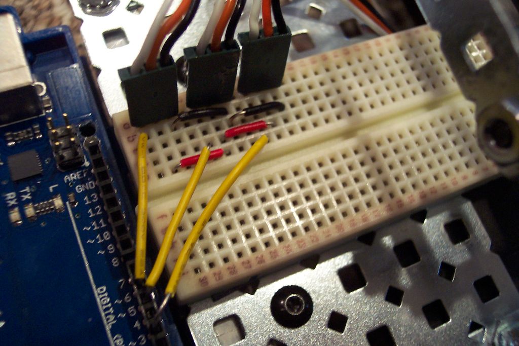
1x Tiny Breadboard (This is optional as you can just wire things directly to the arduino, but it help plan the paths out.)
1x Single-Axis Accelerometer (Optional but highly recommended) I’m using one that is twenty years old so really anything will do (they can be found online for cheap). Just remember for our application the lower the g rating the better, mine is +-4g so anything around there will do.
Materials for the body (Use what you have!!!! Those who have a 3d printer, try making a chassis that way. I don’t have access to something like that but the lighter, the better! I used some scrap metal.)
Gears (I used vex ones, these are needed to drive wheels if you are doing a four wheeled design. People with 3d printers can make their own but for those without access lego gears are a possibility if the mounts are drilled out. Be creative!)
Window Markers!
Random bits of wire/screws to hook everything up.
Step 2: Look at That Body
Just as a general reminder, keep it light! The lighter weight, the easier it is to maneuver.
Step 3: Magnets (so attractive)