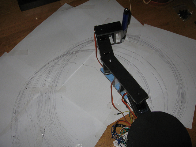
I have constructed a basic Arduino robot arm using 3 servos that cost me £15 in total plus a couple of hours in time to build and it’s very simple that I think anyone can replicate and build this. I already had the Arduino Duemilanove ATMEGA328, some foamboard, tools and glue. The robot arm has 3 joints and moves in the X and Y dimensions – not the Z (although I will build this in subsequent versions). I’ve included some very basic Arduino robot arm code along with robot arm design / blueprints and measurements for you to download and build (on any material).
So firstly, I had a look around for robot arm kits that could be brought rather than fabricating the parts myself – I found the prices to be extremely prohibitive. I then looked at getting a design fabricated but most of the designs I’ve seen rarely give you or decent assembly instructions. I also looked at servo brackets and constructor sets but again whilst the odd piece is OK trying to get the parts for a robot arm is too expensive.
Where does this leave me, apart from being too poor to afford a robot arm kit? Well I thought how hard can it be to design and build my own robot arm? Surely I can do it for less and if it works I can publish the results and schematics rather than just a video of it working. So follow my below steps.
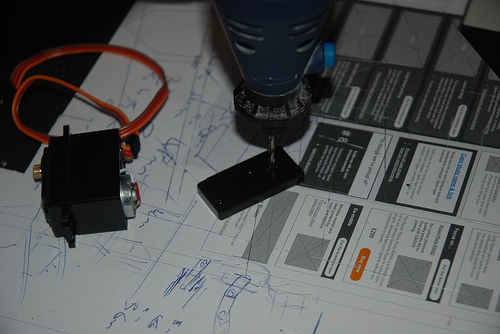
The first problem of designing your robot arm is how do you mount the servos? Most kits tend to use some kind of bracket that the servo is mounted into, the armature then mounted to this bracket. For a simpleton like me this seems like a lot of effort, my workshop skills not being that great and neither is my patience, I didn’t want to go down this route. After much thought I hit upon a simple idea, rather than build a bracket, how about altering the servo casing its self. They’re made from ABS plastic, they’re cheap and tough enough that drilling a hole to create a mounting peg should be easy, the drawing below shows where I added the bolt at the bottom, although measurements only show the nut the bolt is about 8mm in length – all depends on how thick your material is you’re using for the arm.
As you can see from the photos below, I take the base of the servo off and drill a hole in about the same position as the servo shaft at the top, this then allows me to place the servo directly into the armature using a bolt through the base of the servo so that it can turn freely in the arm without needing a bracket.
Robot Arm Servo Modification
Arduino Robot Arm Design
Once this problem is overcome, the rest is easy. You can use my robot arm design below, click on the image to download the PDF:
Just print this off and stick it to the material that you’re cutting then cut the shapes out, if you’re using something more rigid than foamboard you won’t need the cross supports I added. I’ve also included a measurement of my servo in the diagram and remember to alter the measurements for the thickness of your material if needed (My foamboard was 5mm thick).
Read more: Arduino Robot Arm – LarryArm v0.1