The lunch decider wheel is basically a carnival-style wheel that spins every day at 11:45am and selects what is for lunch. It came about on account of my perpetual indecision on this very important culinary matter. In fact, this device does more than just decide what I should eat for lunch, but provides two very important public services. For starters, it selects what everyone will be having for lunch; eliminating the need for surplus cognitive work. Secondly, it prevents me from asking all of my fellow coworkers what I should be eating for lunch (much to their relief).
This project uses some serious hardware such as an industrial-scale magnetic clutch that I purchased directly from a Chinese factory and a 400w laser cutter that I used to cut up the plywood. Of course this project can still be built without these things. It would just require slight modifications to the design and construction process. I did not exactly reinvent the wheel; I just automated it and forced it to pick lunch for me.
Step 1: Go Get Stuff
(x1) 12V DC car seat motor (or similar)
(x1) 24V magnetic clutch (aliexpress)
(x1) Arduino Uno (Radioshack #276-128)
(x1) PC Board (Radioshack #276-150)
(x2) 12V relay (Radioshack #275-001)
(x2) TIP31 transistor (Radioshack #276-2017)
(x1) SPST momentary pushbutton (Radioshack #55050585)
(x1) LM7805 5V regulator (Radioshack #276-1770)
(x1) 10uF capacitor (Radioshack #272-1025)
(x1) 0.1uF capacitor (Radioshack #272-135)
(x2) 1N4004 diodes (Radioshack #276-1103)
(x1) 10K resistor (Radioshack #271-1126)
(x2) 1K resistor (Radioshack #271-1118)
(x12) Quick connects (Radioshack #64-3131)
(x1) M-type power jack (Radioshack #274-1569)
(x1) 12V @ 2.5A power supply (Radioshack #273-318)
(x2) 12V rechargeable batteries (Radioshack #23-943)
(x1) DS1307 real-time clock module
(x1) Clacker
(x36) Pegs
(x1) 1/2″ x 3″ metal tube
(x1) 3″ nylon pulley
(x1) 3D printed pulley (print file)*
(x1) 3′ x 3/8″ round belt
(x3) 6-32 x 1″ spacers
(x4) 4-40 x 1″ bolts and nuts
(x8) 6-32 x 1″ bolts and nuts
(x12) 1/4″ bolts
(x8) 1/4-20 x 1″ bolts
(x2) 4 x 8 x 3/4 plywood sheets
(x1) 4 x 8 x 1/4 plywood sheet
(x1) Assorted shrink tube
(x1) Assorted zip ties
*If you do not have a 3D printer, you can get one from Radioshack or have the part printed using a service like Shapeways.
Step 2: Cut Wood
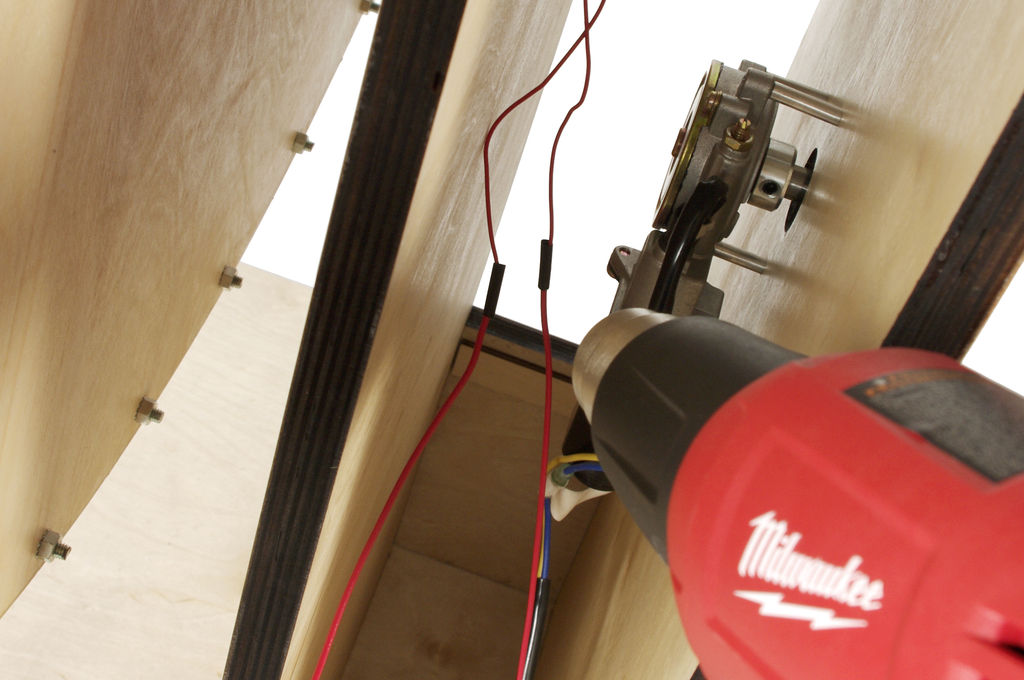
However, I understand that most of you don’t have access to a 400w laser cutter able to blast through 3/4″ plywood with a giant laser beam. Please keep in mind that you can cut these wood pieces the old fashioned way with power tools like saws and drills.
Even though the future is now upon us, you fortunately still don’t need a laser to follow plans and cut plywood. Download the attached files for plans and dimensions of what needs to be cut, and then cut it out.
 wheelBack.eps5 MB
 WedgeTemplate.ai1 MBmotorbracket.eps2 MBfrontBracket.eps5 MBdiscSpacer.eps408 KBComponentbase.eps692 KBbase.eps5 MB
Step 3: Motor Shaft Extension
Step 4: Mount the Clutch
Insert the clutch into the mounting hole and then place the other part of the pedestal horizontally on top.
Insert the corner brackets at each of the corners.
Step 5: Bolt
Step 6: Fasten
Fasten them together with wood screws.
Step 7: Measure and Mark
Repeat this on the opposite edge of the base.
Center 2 x 4’s along the inner edge of these lines such that they are parallel to the center slots.
Step 8: Spacers (optional)
Basically, cut the spacers using the attached template, place the casters atop each one, and trace the mounting holes.
Step 9: Drill and Fasten
Once all of the holes are drilled, mount all of the caster in place using wood screws.
Step 10: Attach the Bottom Plate
Center the pedestal support plate on the underside of base such that it covers the mounting slots.
Drill pilot holes in each of the corners of the pedestal support plate and fasten it down with 1-1/4″ wood screws.
Step 11: Attach
Fasten them together by sinking wood screws through the pedestal support plate mounted on the underside of the base up into the bottom of the pedestal.
Step 12: Drill
Drill a 5/8″ mounting hole 1″ from the opposite end of the aluminum bar.
Step 13: Fasten and Press Fit
Now is time to insert and tighten all of the bolts holding the clutch in place.
Also, download and print out the attached plastic spacer. This is designed to fill in the gap between the inner diameter of the wheel’s mounting flange and the diameter of the shaft. This should provide a nice snug press fit between the two parts and keep the wheel centered.
Note: If you don’t have a 3D printer, you can use a service like Shapeways or iMaterialise
For more detail: Lunch Decider Wheel using arduino