by Chr, ( http://www.instructables.com/id/Led-Cube-8x8x8/ )
by SuperTech-IT, ( http://www.instructables.com/id/CHRs-8X8X8-LED-Cu… )
and by das-labor.org, ( http://www.das-labor.org/wiki/Borg3d_Bauanleitung… )
but i think its better and easier.
I started this Project without any skills from soldering toprogramming.
First of all I apologize first for my poor English. Because of this parts of this instructable are German.
Maybe I translate it later.
this happens if you lose
[Video abspielen]
wining looks like this
[Video abspielen]
and these are the effects:
[Video abspielen]
Step 1: The Component list
Deutsch:
Für den Cube:
512x LEDs
10x Versilberter Draht 0.8mm für Platinen und LED Gitter, 7m SILBER 0,8MM
Für die Platinen:
2x Lochraster Platine 160×100 H25PR160
Platine 1, Säule:
3x 36pol. Stiftleiste, gerade,
10x 10pol. Buchsenleiste, gerade, RM 2,54 BL 1X10G8
1x 74HC138 IC
8x 8 fach D-Flipflop 74HCT574
8x Sockel D-Flipflops GS 20P
100x Widerstände 47 Ohm
9x Kondensator 100nF KERKO 100N
1x 16 pin IC Sockel
Platine 2, Ebenen:
8x Mosfet Transistor BUZ11
2x 36pol. Stiftleiste, gerade,
2x 10pol. Buchsenleiste, gerade, RM 2,54 BL 1X10G8
Für Musik:
Ähnlich wie hier: http://arduino.cc/en/Tutorial/tone
1x Arduino Uno
1x 100 Ohm Widerstände
1x Lautsprecher 8 Ohm
2x Widerstände zwischen 1,5 K und 47 K
1x Schalter 2 oder 3 Positionen
1x oder 2x 10K ohm Widerstände
Für den Controller:
1x Playstation controller
Für Gehäuse:
1x kleine Tube Plexiglas Kleber transparent
1x Plexiglas ca. 405x405mm (for the top)
4x Plexiglas ca. 400x400mm
Genug Holz für den Unterbau und die Schablone
Und:
1x Steckerschaltnetzteil SNT 2500 (5V)
1x Arduino Mega 2560 R3
Und natürlich eine Menge Lot Draht und Kleinzeug.
English:
for the cube:
512x LEDs
10x Silver plated wire 0.8mm for sinkers and LED grid
for the sinkers:
2x Breadboard 160×100 H25PR160
for sinker 1, pillar:
3x 36pol. Male connector, straight,
10x 10pol. Female connector, straight, RM 2,54 BL 1X10G8
1x 74HC138 IC
8x 8xD-Flipflop 74HCT574
8x socket D-Flipflops GS 20P
100x resistors 47 Ohm
9x capacitor 100nF KERKO 100N
1x 16 pin IC socket
for sinker 2, layers:
8x Mosfet Transistor BUZ11
2x 36pol Male connector, straight,
2x 10pol. Female connector, straight, RM 2,54 BL 1X10G8
for the sound:
similar to this: http://arduino.cc/en/Tutorial/tone
1x Arduino Uno
1x 100 Ohm resistor
1x Speaker 8 Ohm
2x resistor between 1,5 K and 47 K
1x switch 2 or 3-positions
1x or 2x 10K ohm resistor
for the controller:
1x Playstation controller
for the case:
1x small tube of adhesive acrylic glass transparent:
1x acrylic glass ca. 405x405mm (for the top)
4x acrylic glass ca. 400x400mm
Enough wood for the base and the template
and:
1x SNT 2500 (5. Female connector, straight power supply)
1x Arduino Mega 2560 R3
and a lot of wire, solder and other little things you find somwhere
Step 2: Build the Cube
Deutsch:
Den Cube baute ich nach der Anleitung von das Labor denn dies ist etwas einfacher als nach der Methode die hier in den Anleitungen kursieren.
http://www.das-labor.org/wiki/Borg3d_W%C3%BCrfel_…
1. Schablone für je 8×8 LEDs bauen
– Größe für den Cube überlegen
Ich entschied mich für 4cm Abstend zwichen den LEDs also eine gesamt größe von ca 28cm
Die Holzplatte zur Herstellung sollte dem entsprechend gößer sein.
– 8 Nuten senkrecht fräsen mit einer Tiefe von 7mm und einer Breite von ca 3mm
– 8 Nuten senkrecht fräsen mit einer Tiefe von 1- bis 2mm und einer Breite von ca 3mm
– Für die LEDs muss noch 2mm über jeder Kreuzung eine Vertiefung für die LED gemacht werden
English:
I build the cube itself after this:
http://www.das-labor.org/wiki/Borg3d_W%C3%BCrfel_B…
It’s much cuter than intractables I’ve seen on this site.
1. Build a Template for 8×8 LEDs
– Consider the size for the cube
– I chose 4cm as the distance between the LEDs yielding to a total size of approx 28cm
The wooden plate for making should be bigger according to the following.
– 8 grooves milled vertically to a depth of 7 mm and a width of about 3mm
– 8 grooves milled vertically to a depth of 1 – to 2 mm and a width of about 3mm
– Still a 2mm recess for the LED needs to be done about every intersection for the LEDs
Step 3: Build the sinkers
German:
Die Platine baute ich ebenfalls nach:
https://www.das-labor.org/wiki/Borg3d_Platinen_Bau…
Doch ich entschied mich später so um zubauen wie es bei chr (Step 9) beschrieben wurde.
Von der Platine mit mc nutze ich nur noch die Transistoren, denn als mc verwendete ich einen arduino uno bzw. mittlerweile einen arduino Mega.
Den Cube selbst kann ich wie auch schon bei chr beschieben mit allen Effeken auf einem arduino uno laufen lassen, allerdings wollte ich noch einen Playstation controller nachrüsten, deshalb änderte ich das Programm auf die Hardware für den Arduino Mega.
Englisch:
The board I built also by:
https://www.das-labor.org/wiki/Borg3d_Platinen_Bau…
But later I decided, however, to assemble the board with mc as described by chr in (Step 9).
From the board, I only use the transistor circuit, because as mc I used an arduino uno and now a arduino mega.
The Cube itself I can already run like chr with all effecs on arduino uno, but I still wanted a Playstation controller upgrade, so I changed the program to the hardware for the Arduino Mega.
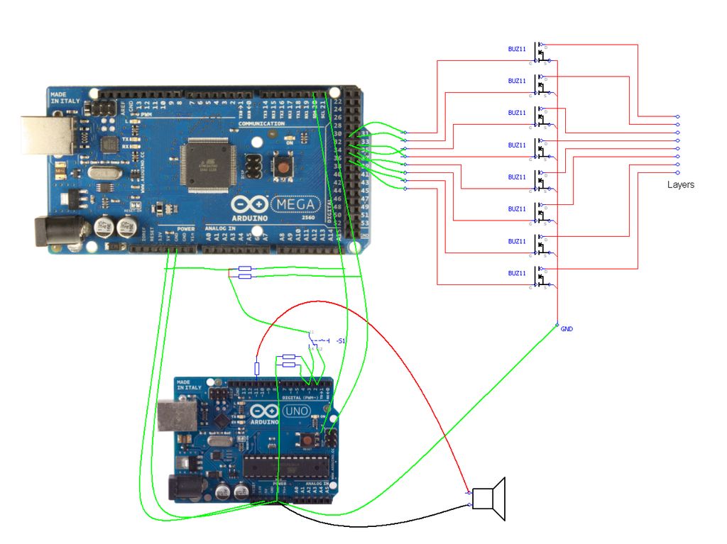
On the wiring diagram i am still working. This will take some time and follows later. I changed too much too many times. It´s a mix from chr and das-labor. But easyer.
Step 4: PIN wiring
Please check the pictures, how to connect the mega to the sinkers.
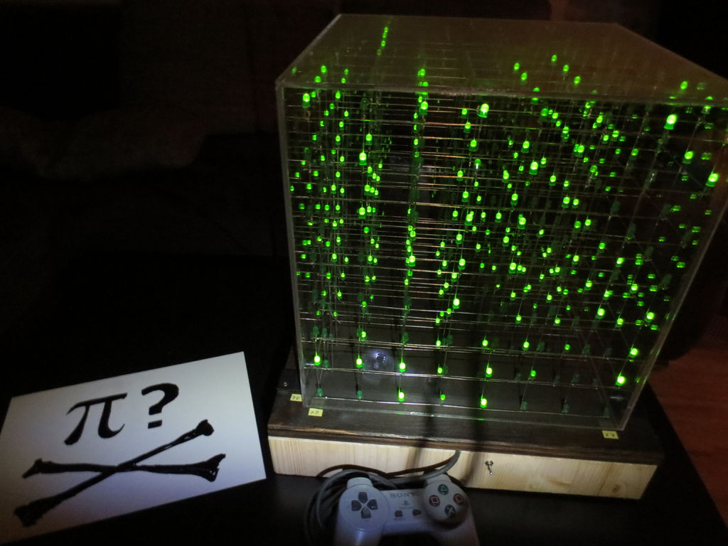
Step 5: Build the case, power supply etc…
see the pictures
the cube has a acrylic glass hood made with 5 pieces of acrylic glass and a bit glue
1x ca 405x405mm (for the top)
4x ca. 400x400mm
you will figure it out
but test it before gluing and read first how the glue works (my glue cures only by blacklight)
i made the rest out of boards laying around
Step 6: Programm (Arduino Mega setup)
Vorerst hier nur die Änderung im setup für den Arduino Mega:
ursprungscode von chr
http://www.instructables.com/id/Led-Cube-8x8x8/ (step 70)
Here you find the changes I made to his code. (from Arduino UNO (like chr) to Arduino Mega)
void setup()
{ int i;
//Pins 22 bis 50 als Ausgänge festsetzen
for(i=22; i<50; i++) pinMode(i, OUTPUT);
// pinMode(A0, OUTPUT) as specified in the arduino reference didn’t work. So I accessed the registers directly.
DDRC = 0xff;
PORTC = 0x00;
// Reset any PWM configuration that the arduino may have set up automagically!
TCCR2A = 0x00;
TCCR2B = 0x00;
// zähler, Uhr initialisieren
TCCR2A |= (0x01 << WGM21); // CTC mode. clear counter on TCNT2 == OCR2A
OCR2A = 10; // Interrupt every 25600th cpu cycle (256*100)
TCNT2 = 0x00; // start counting at 0
TCCR2B |= (0x01 << CS22) | (0x01 << CS21); // Start the clock with a 256 prescaler
TIMSK2 |= (0x01 << OCIE2A); //Timer Interrupt Mask Register
}
//interrupt
ISR (TIMER2_COMPA_vect)
{
int i;
// PORTA = 8x Databus (8-Bit-Latches) PIN 22-30 (bei uno Pins 0-7 PortD)
// PORTL = 3x Adressbus + OE
// PORTC = 8x Ebenen (Layer)
// Char cube [ 8 ] enthält 64 Bits von Daten für die Halteanordnung
// all layer selects off
PORTC = 0x00;
PORTL &= 0x0f; // PortL 3xAdressbus
PORTL |= 0x08; // output enable off.
// Zählen bis 8
for (i=0; i<8; i++)
{
PORTA = cube[current_layer][i]; //(PortA = 8xDatabus) PIN 22-30 (bei uno Pins 0-7 PortD)
PORTL = (PORTL & 0xF8) | (0x07 & (i+1)); // (i+1) => 74HC138 erhält die folgende Sequenz: 1 2 3 4 5 6 7 0 (muss immer eins voraus sein)
}
PORTL &= 0b00110111; // Output enable on.
//ebenen
if (current_layer < 8)
{
PORTC = (0x01 << current_layer);
}
current_layer++;
if (current_layer == 8)
current_layer = 0;
}
Step 7: Programm PSX
#include psx
diese library kann man unter:
load it here:
http://playground.arduino.cc/Main/PSXLibrary
you have to change parts in this lib for the new Arduino IDE (I used 1.0.5) if you want to use a old Playstation controller!
you might also can use a ps2 or ps3 controller but then you need a other library.
Vor dem importieren muss allerdings eine Datei manuell angepasst werden da die PSXLibrary nicht für die Arduino IDE 1.0.5. angepasst wurde.
Because PSXLibrary ist not combatible with Arduino EDE 1.0.5 a file has to be adjusted before import like this:
Dazu die Herruntergeladene Datei öffnen – open the downloaded file
den ordner PSX öffnen – open the PSX
Die Datei PSX.h öffnen – open the PSX_h file
dort den Befehl #include “WConstants.h” – change #include “WConstants.h”
ändern zu #include “Arduino.h” – to #include “Arduino.h”
speichern – safe
nun sollte die Ardunio IDE keine Probleme mehr beim kompilieren machen.
after this it should compile.
Pin verdrahtung:
#define dataPin 50 //PS-Pin 1 brown
#define cmndPin 51 //PS-Pin 2 orange
#define attPin 52 //PS-Pin 6 yellow
#define clockPin 53 //PS-Pin 7 blue
//PS-Pin 4 GND black
//PS-Pin 5 VCC 3V red
For more detail: 8x8x8 LED Cube with Arduino Mega (+Sound +PS controller +Game)