I originally wanted to purchase a Nebulophone but, my El-Cheapo price range didn’t like the tag. I realized that I could program my own AtMega 328 by using ArduinoISP Then I found out that if the code was Arduino compatible, why not just use the Arduino as a Nebulophone? Well it was kind of a waste of Arduino but at least I could simplify circuitry. I recently built my DoAnything Shield and could now have access to any pin I wanted.
I looked at the schematic and realized that Dr. Bleep had left plenty of things missing such as where did the stylus go and, where were the keypads and so I emailed him and after a long string of emails everything was cleared up.
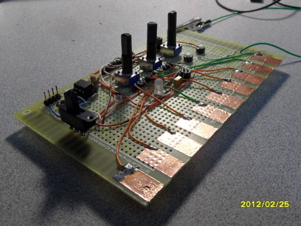
I don’t have that many photos but the photos I did take explain a lot.
Step 1: The Bits and Pieces Needed
10cm of copper tape (You should get 11cm in case of any trouble…Really any measurement will work; you just need to make it fit your board)
1 alligator clip
1 SPST/SPDT slide switch (Any type of switch that can move from one position to another until pused again work (Toggle, Rocker, etc.) It doesn’t matter whether it is SPST or SPDT the second connection is nothing.)
2 Pushbuttons (Tactile works nicely.)
1 5mm LED (Really any size will work. This is the Arpeggio LED)
1 LED and Photocell assembly (I got mine from here but I didn’t realize that the same website had this which is much cheaper although untested. You could also make your own by bending an LED over to a photocell that can range from 10k to 200k. and then covering it with some black tubing. I’m not sure the one I had is exactly 10k to 200k but it worked.)
1 speaker and amplifier
1 Rail to Rail Op-Amp (the article said tlc2262 but I improvised with tlc2272 and it works fine. IT MUST BE A RAIL TO RAIL OP-AMP)
1 row of male headers
1 DoAnything Shield (Really it is only an adapter…you don’t have to use one.)
1 Piece of Large PerfBoard (This or this SHOULD work.)
3 0.1uF Capacitors
1 220uF Capacitor
1 8 pin IC Socket
1 Audio Jack (For output. You should use the size that fits your speaker and amplifier)
1 Power Supply (For the Arduino, of course. (9v battery, USB Cable, Wall Wart, etc.))
1 IR LED (Use the clear side-firing type) (I didn’t add this; I don’t own any other Andromeda Space Rockers or Gieskes )
1 IR PhotoTransistor (See IR LED)
1 HUGE BUNDLE OF WIRE (You will need both solid and stranded wire.)
1 Arduino
Step 2: Program.
REMEMBER: This is a large sketch. If it takes longer than a millisecond to program it it is because it is so big.
If all goes well, then you should have a dim flicker from the built-in LED on Pin 13.
Save the code in your Arduino Sketchbook fol
 Nebulophone_D01.zip121 KB
Step 3: Build.
This is the tougher part. I have less photos here so I am sorry but I will do my best to explain thoroughly.
The first picture is the circuit. Click on the “i” in the upper left hand corner to view the circuit better.
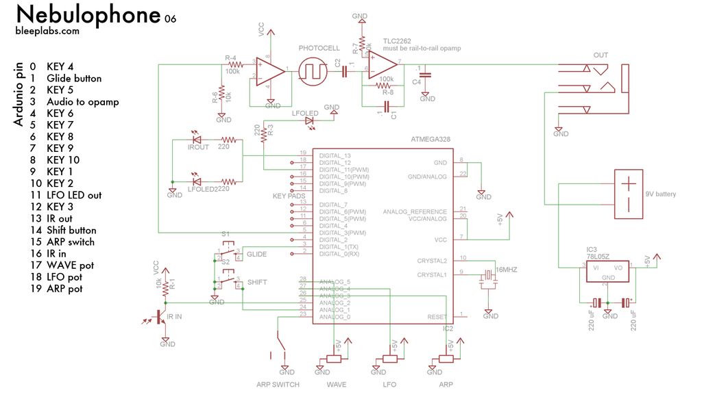
NOTE: I will assume you have found a way to bypass the fact that the distance between Digital Pin 7 and Digital Pin 8 is not the standard 0.1″.
- Take your male headers. You will want to move them towards the shorter side. This will enable it to plug into the Arduino more easily.
- Solder them face down so that the long side protrudes below the board as in Picture Three and Four. The black holder should be above. Next, solder the headers down.
- You can now start placing components according to the schematic.You can follow my layout, Dr. Bleep’s layout or your own layout.
- The way I soldered wires to connection was I took the wire and stripped the end and wrapped it around as in Picture 8. I then soldered it as in Picture 9.
- Now comes the tedious part. Take your copper tape and with a small knife (X-acto) Score at an interval. Because I had 15 cm to use I had 1 cm pieces with 0.5cm in between each one. (Approximately.)
[box color=”#985D00″ bg=”#FFF8CB” font=”verdana” fontsize=”14 ” radius=”20 ” border=”#985D12″ float=”right” head=”Major Components in Project” headbg=”#FFEB70″ headcolor=”#985D00″]3 Potentiometers
3 0.1uF Capacitors
1 220uF Capacitor
1 8 pin IC Socket
1 Audio Jack
1 Arduino[/box]
For more detail: DIY Arduino Nebulophone Synth