Overview
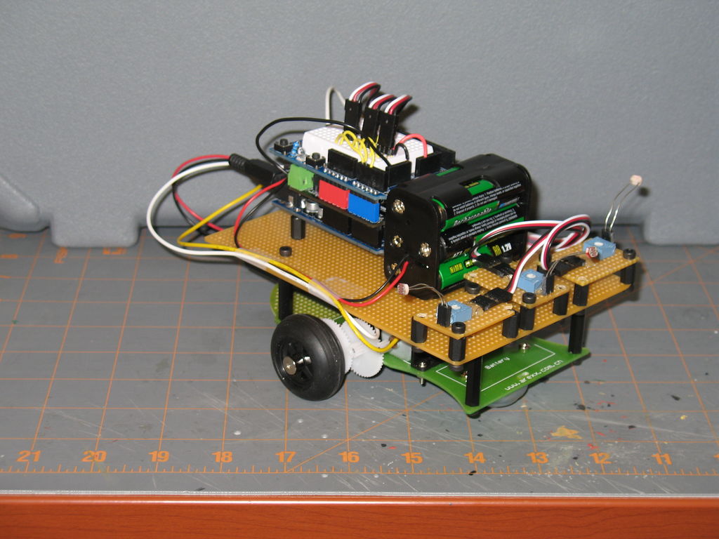
This instructable will use three photoresistors (light dependent resistors) and an Arduino to control the motion of a robot. Any common robot chassis can be used for the robot. The light sensors will be mounted on the left side, right side and front of the robot. When light of sufficient intensity falls on a sensor, the robot will respond with a left turn, right turn or forward movement, corresponding to the location of the sensor that is activated. The instructable will also pass along some electronics tips that I have found useful and, hopefully, will prove useful to others.
Step 1: List of Materials
List of Materials:
3x Light Dependent Resistors
http://www.jameco.com/webapp/wcs/stores/servlet/Product_10001_10001_202403_-1
3x 250K trimmers (potentiometers)
http://www.jameco.com/webapp/wcs/stores/servlet/Product_10001_10001_2200903_-1
3x Three pin sensor cables
http://www.trossenrobotics.com/robotgeek-3pin-sensor-cable
1x Duemilanove or compatible Arduino board http://www.freetronics.com/collections/arduino/products/eleven#.UzImtdhOWM8
1x DFRobot motor shield
http://www.dfrobot.com/index.php?route=product/product&filter_name=motor shield&product_id=69#.UzInGthOWM8
1x Arduino proto shield
http://www.adafruit.com/products/51
1x Robot Chassis
http://www.hobbyking.com/hobbyking/store/__26248__Simple_Expandable_Robot_Chassis_KIT_.html
2x 4”x6” Proto boards
http://www.elexp.com/ProductDetails.aspx?item_no=03013404&CatId=a936becc-2bfd-49bb-b59b-7c07715dbfea
Various standoffs and hardware. A good kit can be found at
http://www.dfrobot.com/index.php?route=product/product&path=46_99&product_id=700#.UzIrrNhOWM8
The standoffs used in this instructable are from a Trossen Robotics robot kit. The standoffs and hardware are also sold individually
http://www.trossenrobotics.com/standoff-variety-pack
http://www.trossenrobotics.com/nut-and-bolt-pack
1x 6AA battery holder
http://www.digikey.com/product-detail/en/BH26AAW/BH26AAW-ND/66737
1x 9V battery holder with barrel plug
http://www.adafruit.com/products/67
Finally, we will need some male and female headers
http://www.jameco.com/webapp/wcs/stores/servlet/Product_10001_10001_308567_-1
http://www.jameco.com/webapp/wcs/stores/servlet/Product_10001_10001_2076869_-1
Step 2: Robot Platform
Robot platform preparation. As mentioned, any common chassis can be used for the robot, and I chose the Arexx robot chassis listed above. This chassis had a rather small upper deck, thus the need for one of the proto boards. Put four 3cm (or similar) standoffs on the existing holes on the lower deck of the chassis, and then position the proto board on top of the standoffs to form the upper deck. Mark and drill screw holes. See accompanying photo. This gives us a platform that we can drill screw holes into to hold various electronics and sensors. This platform can be reused with other sensors in future robot projects.
Step 3: Light Sensor Platforms
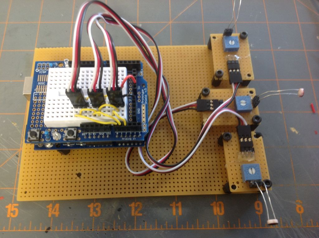
Next we need to construct the light sensor platforms. One proto board was used for the upper deck of the robot. From the second proto board, use a hobby saw or Dremel to cut three 1.5cm by 2.5cm rectangles. In each corner, drill a screw hole. These small boards will hold the electronics of our light sensors. Before we add the electronics, position the small boards on the upper deck of the robot as shown in the accompanying figure. Mark, drill holes, and add 1cm standoffs to attach the small boards to the upper deck. At this time, you may also want to decide on the position of the Arduino board on the upper deck and drill appropriate screw holes. Also add some 1cm standoffs to hold the Arduino. Leave enough room between the Arduino and the light sensors to insert the AA battery holder.
Step 4: Light Sensor Electronics
Now for the electronics for the light sensors. Each light sensor will consist of a voltage divider made from a photoresistor and 250K trimmer. First, from the female header strip, cut three pairs of headers. From the male header strip, cut three sections of three headers each. See accompanying picture. Bend the male headers, if needed, to form a right angle. Before soldering anything, the first thing I did was hot glue one female header pair, one three pin male header and one 250K trimmer to each small proto board. See accompanying figure. On the back of the protoboard there will be two leads from the female header, three leads from the trimmer, and three leads from the male header as seen on the far right in the accompanying figure. Before soldering, it may help to bend the leads of the trimmer as shown in the accompanying photo. Solder the leads as follows. One section of wire (white in the photograph) will connect the wiper lead of the trimmer to the far right leads of the male and female headers. A second section of wire (red in the photograph) will connect the left female header lead to one of the remaining leads of the trimmer and the center lead of the male header. A third section of wire (black in the photo) will connect the remaining lead of the trimmer to the left most lead of the male header. Finally, insert a photoresistor into the female header on each small proto board.
The advantage of this voltage divider is that it can be adjusted with a small screwdriver via the trimmer. Thus the sensitivity of the light sensor can be changed independent of the Arduino code (contained below). Also, these small platforms can now be used as light sensors for future electronics projects. In addition, other types of electronics can be put onto the small 1.5cm x 2.5cm proto boards; LEDs, piezo buzzers, buttons, lasers, etc. Since all the small boards will be the same size, they will be interchangeable on the robot deck, giving many possibilities for different robot configurations. I am currently constructing several such boards and a customized Arduino shield for a future Instructable.
For more detail: Arduino Light Following Robot