This is a Spring 2014 Electronics project at Pomona College created by Andreas Biekert and Jonah Grubb. Thanks to Professor Dwight Whitaker, Tony Grigsby and the Pomona Physics Department.
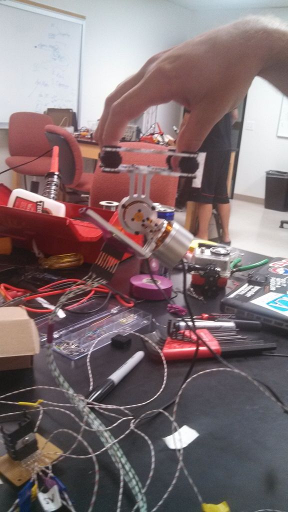
Our goal with this project was to create a 2 axis brushless gimbal controlled solely by an Arduino Uno with input from an accelerometer/gyro. A gimbal is a camera stabilization system that uses motors to correct unwanted camera motion. The goal is to create perfectly steady footage, although smoothing out any bumps is a reasonable first benchmark. “Brushless” refers to brushless motors which we will explain more about later. All the other gimbal projects we found are controlled using fabricated gimbal control boards so we wanted to approach the project from a more fundamental level. Our hope was to create brushless gimbal control without this kind of board, but rather using the more general purpose Arduino Uno.
We’re going to have to be upfront; we never got the gimbal we were looking for. However, we did learn a lot about how the device should work, so we have written our thoughts on improvements and directions to pursue with the project. We hope this is at least a good resource for a starting point. Let us know if you have any questions or suggestions for improvement.
Between learning how to control the brushless motors and interfacing with the accelerometer we consulted quite a few sources for this project. We will be referencing material and using photos from this project, which served as our foundation for brushless motor control. Our code is heavily based on both the aforementioned motor control project and this I2C library with sample code for an MPU6050 chip. A big thanks to both of these projects for giving us direction in our efforts!
There are several ways to go about getting the parts for this kind of project. Naturally, one of the principle components is the Arduino Uno.
We bought a frame and brushless motor set on Amazon: Frame and Brushless Motors. It’s probably possible to machine or print your own frame, but we were more interested in the electronics portion of this project, so we went with the quicker route of simply buying the frame ready-made.
We also bought our accelerometer off Amazon: Accelerometer/gyro. The GY-521 breakout board is significantly cheaper than any other MPU6050 models we found, but it worked just fine for our project. However, we did manage to break one and had to order another one. We still aren’t sure if its failure was our fault.
We used two Mauser 511-L298 h-bridges (with heat sinks) to control the motors—more on that later. These are able to handle the higher voltages and currents needed to drive the motors so they can move the frame and camera.
Some other small components we used were two 2.2k resistors, three 0.1 microFarad capacitors, and a lot of wiring 🙂
Step 1: Brushless Motor Control (Part 1 – Concepts and Theory)
Brushless DC motors are ideal for this project because they are efficient, precise, and have plenty of torque; the trick is actually controlling them. The most common hobby route is to buy programmable electronic speed controllers which can take throttle inputs and convert that to rotational speed in the brushless motors. However, these can cost $20 for the cheapest ones, so we decided to save costs and figure out how to control the motors without them.
Unlike brushed DC motors, which work by simply reversing the current in loops of wire in a permanent magnetic field via a commutator, brushless motors have no physical connection between the wire coils on the stator and the rotor. The most common brushless motors are known as three phase brushless motors. This means that they have three distinct sets of coils, often labelled A, B, and C. Surrounding these are permanent magnets with alternating orientations.
Our motors have twelve coils or electromagnets (3 sets of 4) and fourteen permanent magnets on the rotor. The idea is that we change the polarity of our electromagnets in a cycle and the permanent magnets follow the changing magnetic field. In the simplest form, we have three electromagnets (A, B, and C) and the rotor is just a single NS permanent magnet. If we have coil A creating a north magnetic field and coil B creating a south field and coil C off, the magnet will turn to align itself as closely as it can to the generated magnetic field. We can then rotate the polarities of our electromagnets by one position (A off, B North, and C South) and the magnet will follow. In this manner, we have a set of commutation phases that when we run them in order cause the rotor to turn, and we can reverse this cycle to run it in the opposite direction.
Watch these two videos for a clean and clear explanation with diagrams.
We did some research and found that sending Sine waves that are 120 degrees out of phase through the three sets of electromagnets, we can create a dynamic magnetic field that drives motor rotation. Introducing a sinusoidal signal smooths out the motion of the motor considerably by changing the polarity of the electromagnets gradually. This site was very useful in taking that theory and turning it into Arduino software. The trick to this approach is running our PWM signal from our Arduino through an H Bridge to allow negative polarity of one of the coils since PWM signals only output High (1) and Low (0).
One of the biggest challenges of brushless motors is that to properly control them you need information of where the rotor is in reference to the stator coils. That way the controller knows exactly where in the commutation cycle to begin or to jump to. We were hoping that the accelerometer may be able to give this feedback, which seemed to work with moderate success. More sophisticated methods include attaching hall effect sensors to detect the position of the rotor or even using the “back emf” induced in the coils.
Step 2: Implementing Brushless Motor Control
Introducing the h-bridge to control the motors allows us the bi-directional motion that the gimbal requires, and also allows for very smooth stepping of the motor’s position. The H bridge essentially flips the sign on one of the electromagnets so that we can have a high, a middle and a low voltage. As mentioned in the introduction, we used L298 h-bridges, which have 15 pins. We wired each of them as seen in the image above. Here is the data sheet.
- Pin 1: Ground
- Pin 2: Motor Pin 1
- Pin 3: Motor Pin 2
- Pin 4: External Supply Voltage (put a 0.1 microFarad capacitor to ground)
- Pin 5: Arduino PWM Digital Output (pin 3 or 9)
- Pin 6: +5V from Arduino (put a 0.1 microFarad capacitor to ground)
- Pin 7: Arduino PWM Digital Output (pin 5 or 10)
- Pin 8: GND
- Pin 9: +5V from Arduino
- Pin 10: Arduino PWM Digital Output (pin 6 or 11)
- Pin 11: +5V from Arduino
- Pin 12: Not Connected
- Pin 13: Motor Pin 3
- Pin 14: Not Connected
- Pin 15: GND
Our source describes a clever scheme of approximating a sinusoidal signal to the motors. They construct an array of 48 values between 0 and 255 which represent the values of the sine function at equal increments. They begin each electromagnet state A, B, and C 16 values apart from one another, which divides the period of the function into thirds or, in other words, phase shifts the states by 120 degrees. Then, they simply increment each state’s value in the array so that the states cycle through the sine wave with each loop of the program. The result is very smooth rotation in the motor, although it is somewhat speed limited by the physical ability of the motor to keep up with the Arduino signals.
We use the same PWM sine-array scheme as our source, which allows to increment though a numerical approximation of the sine function over a given number of steps in the period. In our case, we doubled the number of values in the array from 48 to 96 so that we could more precisely control the motor. This is because our gimbal application does not need the motor to make full rotations, well, ever; we only need to adjust the camera’s position against the motion of the base. Quick observations suggest our scheme allows the motor to step in 0.2 degree steps at a time.
It’s important to note that this is mostly a makeshift way of controlling brushless motors. At any given moment, we want one electromagnet high current, one low, and one in a high-impedence state, which approximates to neither high or low. In our case, the “high-impedence” state actually lets current run off to ground, which generates a significant amount of heat in the motor. A definite place for improvement is to keep the motors from getting hot in the case of long-term (e.g. over a minute or two) operation.
Another hazard with our implementation is in the case that the motor physically misses or overshoots one of the steps, which can happen given the significant weight of the frame and camera relative to the motor’s torque. In this case, our program is unaware that the motor isn’t in sync with the signals, and cycles through the sine wave once before “catching” the motor and resuming normally.
Step 3: Using the Accelerometer and Gyro
The accelerometer allows the Arduino to understand the position of our camera at any given time in reference to gravity and detects axial accelerations. The gyro detects changes in angle. With this data we created a servo (a feedback loop that approaches a given set point) to keep the gimbal at a fixed position. We used the MPU 6050 6-DOF (Degree of Freedom) Accelerometer and Gyro mounted on the GY 521 breakout board.
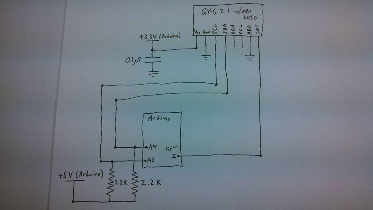
We wired the accelerometer to the Arduino as seen in the picture above. Unfortunately there is no data sheet for this breakout board. This is what we found in the comments on Amazon:
- VCC: +3.3V From Arduino (attach 0.1 microFarad capacitor to ground)
- GND: GND
- SCL: A5 on Arduino Uno (With 2.2k pull up resistor to Arduino +5V)
- SDA: A4 on Arduino Uno (With 2.2k pull up resistor to Arduino +5V)
- XDA: Not connected
- XCL: Not connected
- ADO: GND
- INT: Digital Pin 2 on Arduino
We searched around and found some Arduino sketches that give you the raw data. However, this is pretty noisy and not particularly useful, especially in servo-ing. The MPU 6050 has a built in Digital Motion Processor (DMP); however, instructions on using it are not provided. Some brilliant person at MIT (thanks Jeff Rowberg!) reverse engineered the chip and figured out how to activate the DMP and get the clean and steady data from that. We used his code which allowed us to receive the data in several different forms including Euler Angles, Quaternions or Yaw Pitch and Roll (YPR).
For more detail: Brushless Gimbal with Arduino