Background
This robot is one I built to learn. Before this project I did get my feet wet with a few small scale Arduino projects like an ultrasonic robot, (that would move backwards until it was a certain distance away from the wall,) and I did get to play with a few of the shields designed for the Arduino, but I had never built a full scale project with this microchip, or really, any microchip. I knew if I was going to continue on this journey of being a hobbyist I would have to fully understand the Arduino inside out. I wanted a project that would accomplish my goal, (or just get closer to my goal of fully understanding the Arduino,) and one that would be useful or fun to play with after completion! The project that would help me do just that was the Robo-Mobile.
Overview
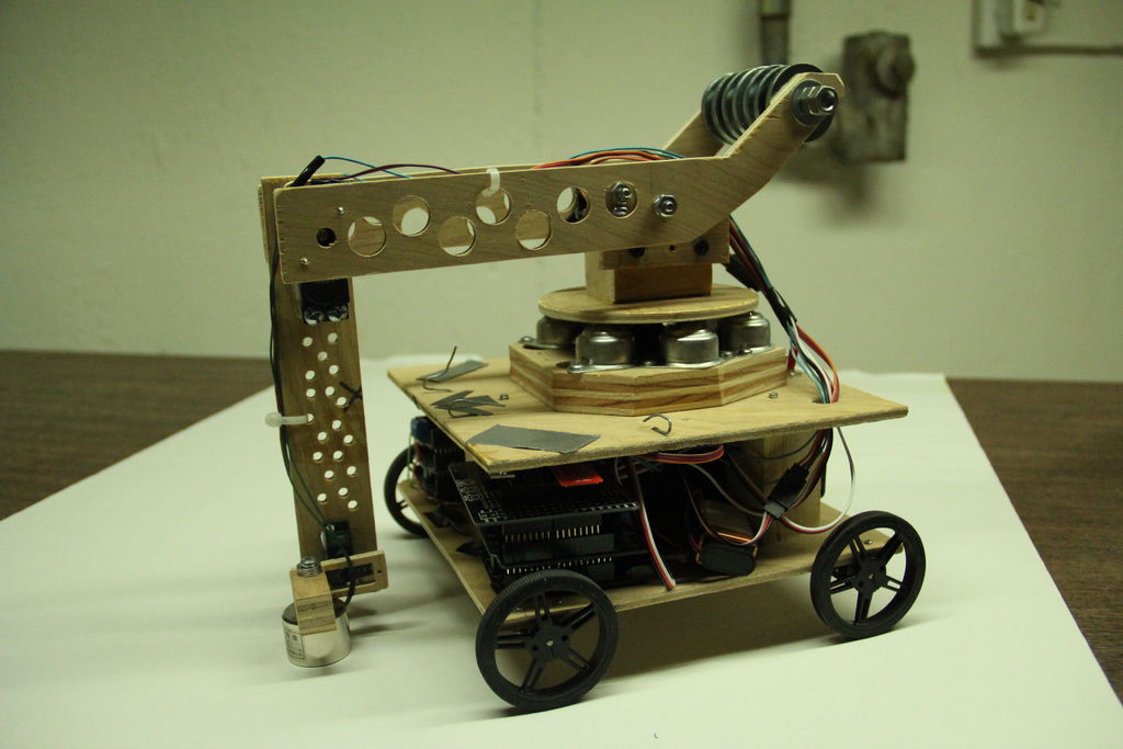
The Robo-Mobile consists of two parts: a chassis and a robotic arm. The arm was designed to be able to pick up items, move them, and drop them in specific places. It was also designed to have a solid range of motion and should be able to move objects with reasonable weight. This arm would then be mounted on a chassis that can then move around like a car. Since the chassis was easier to make, I will be starting this Instructable with the chassis, and I will move to the robotic arm afterwards. This robot was built purely from scratch. (Okay, maybe not the motors, or the Arduino, or the wheels, etc. But no kits or pre-built robot arms or chassis are used in this robot.)
Contests
There are many contests that I have entered this Instructable in. One contest I really have hopes up for is the Full Spectrum Laser Contest. I know that there are over 1000 entries and that I am really late, but if you like my Instructable please give me a vote. If I were to win the 3d printer or laser cutter I could greatly improve my robots and other projects.Thanks in advance!
Step 1: Choices
There were many choices I made throughout the process of building this robot. But in this Instructable I am going to put the bigger and more important choices I made together, right here at the beginning.
Remote vs. AI
Every robot has to have some way it is controlled, the robot can be computer controlled through some kind of AI loop program, or the robot can be remote controlled, making movements based on user inputs! While making the Ultrasonic robot, (the other project I made with Arduino,) I chose to make an AI loop robot. I knew this time I would have to explore the realm of the remote control to improve my Arduino skills further. (AI loop robots are in fact harder to perfect because they need the ability to react to the outside without a user telling them what to do at every given time. But because I hadn’t already made a remote controlled robot I thought it be interesting if I tried something new. Plus remote controlled robots are more fun to play with after the completion of the project!)
Communication
After deciding that this was going to be a remote controlled robot I needed a way to tell it what to do. I needed a way of communication. For communication, there were a few options. The first one being the old school wired communication. This would have been the easiest method to implement, but wired communication is “Old School,” technology is moving forward and wireless has become a must have for new devices. (Ex. Wireless charging, Cell Phones, Wireless Keyboards and Mice, etc.) Wired communication would also constrain the robot’s range, not allowing it to move without a wire “tail”. The method I chose to use was the well known wireless communication called Bluetooth. I know that remote controlled cars usually use radio frequency and now that I’m looking back at this project I think using radio frequency instead of Bluetooth might have been a better idea for this specific project. But going back to the goal I had in mind, I went with Bluetooth for experience! I felt that other projects I would make in the future with an Arduino would be controlled using smartphones and other Bluetooth devices so I chose to use Bluetooth for this project! (The downside is lag. If I ever made a v2 I would explore with radio signals instead.)
Controller
Now for the controller. I knew I was going with Bluetooth. But making a controller work was a entire different story. Since my robot is really two parts, the chassis and the arm, I chose to split up my controllers too. For the chassis, I used a simple android app to control the movement of the robot. The android app was written by myself using MIT’s App Inventor. (I will go into more detail in one of the next steps.) For the arm, I used a dummy robot arm that the real arm would mimic. When I move one of the joints on the dummy arm, the real arm on the robot would mimic the same position. This method has many benefits which include, ease of implementation and ease of use. If the controller was also a button based android app that moved a single motor one at a time, moving the arm to a specific posture would have been a pain. The only downside of this method was the need to build a 2nd arm which isn’t really that bad considering after building one all you need to do is build a copy.
Material
Before I cut the first piece of my chassis. I had to choose the material my robot would be made out of. As you may have seen from the pictures above that I chose to make mine out of plywood! I know that there are other materials out there that may suit this project much better, but I chose to use wood because I was confident working in wood! I knew how to operate wood fairly well being able to use the basic power tools suiting my needs. (Basic power tools I use include a Drill Press, a Miter Saw, a Jigsaw and a Dremel rotary tool. These tools were the tools I used to make my project but substituting the drill press out for a drill or a hand saw for the other power saws are perfectly reasonable.)
Time to start building!
Step 2: BOM (Bill of Materials)
There were many components in this robot, much more than my old ultrasonic robot had. The list I have is here:
Electronics
- 3x Arduino Unos – one is used to control the arm, one is used to control the car, one used as the dummy arm control board sending signal to the Arduino controlling the arm. (Had one and picked up two more from my local electronics store.)
- 1x Bluefruit EZ-Link Shield – Buying a specific Bluetooth shield wasn’t really necessary but to ease into the Bluetooth I bought this for ease of use. Using breakouts like HC-05 is perfectly fine. (You will see that I did buy HC-05s for the arm and dummy arm because this shield can’t run as master and only as slave. Needs soldering.)
- 1x Adafruit Motor/Stepper/Servo Shield for Arduino v2 – Be sure to get the v2 edition because this shield can run motors up at 1.2 A each. (This is a great shield for the Arduino, needs soldering though.)
- 1x Adafruit 16-Channel 12-bit PWM/Servo Shield – This kit wasn’t really necessary it just made life a little bit easier. Driving the servos for the arm could have worked with just the Arduino. (Needs soldering.)
- 2x ProtoScrewShields – They are both used to make my own shield for the HC-05 and other circuits that weren’t included in the other shields. (Picked up from my local electronics store. This shield isn’t made for Arduino Uno R3 but instead an older model, even though it is missing a few pins it worked in this project.)
- 4x Header Kits – Used to stack shields, I personally used 4 sets because the Adafruit shield kits didn’t come with stackable headers. (1 set for Bluefruit, 1 set for Motor, 1 set for 16 channel, 1 set for spacing out shields to plug servos in.)
- 8x Flip switches – Used to turn on and off the different electronics. (I used 8 of them but it depends on the wiring.)
- 2x HC-05 – A Bluetooth breakout I used to connect my dummy arm with the arm.
- 4x Solar Servos – I bought two D772, one D227, and D653. These had the most torque I could find at a reasonable price.
- 1x Electro-Holding Magnet – This is used as the “Picker” in this project.
- 4x Feedback Servos – I bought three standard sized feedback servos and one mini servo but they essentially do the same thing.
- Wire – A various different kinds of wires were used in this project. Some wires used were specific servo extension wires for organization purposes, but most wires were just “Regular Wire.”
- 4x Battery Packs – I used two 4 AA battery packs, one 6 AA battery pack, and one 8 AA battery pack.
- Batteries – There were many batteries used in this build. I specifically used 22 AA batteries and three 3 9v batteries. The 9vs were used to power my Arduinos when the AAs were used to power the motors and Electro-Holding Magnet.
- 4x Pololu 298:1 Micro Metal Gearmotor MP – These are the main motors for the chassis.
- 7x 9v Battery Snaps – These are used to connect the battery packs I bought to the circuits.
- 3x Arduino DC plugs – These are the basic power connectors for the Arduino.
- Male and Female Headers – Different from the kits these are used to connect breakouts to my self designed circuits.
- Resistors – There are a few different resistors used in this project, they are all used in the self designed circuits.
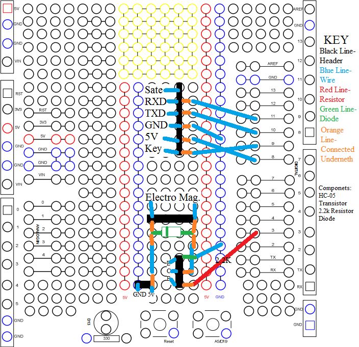
- 1x TIP Darlington Transistor – This is used to control the only “High Powered” component in this build, the holding magnet. (The model # might not be the same. I used a NTE 261 which is essentially the same.)
- 1x Rectifier Diode 1N4001 – Also used to control the holding magnet. (Model # of the equivalent diode I picked up from local electronic store was the NTE116.)
Other Parts
- 2x Pololu Micro Metal Gearmotor Bracket Pair – These are used to mount the motors onto the chassis.
- 2x Pololu Wheel 60x8mm Pair – These are the wheels of the chassis. These wheels are small but fit the robot well. Larger wheels could also work.
- WOOD – If the body is made out of wood. I used some scraps I had laying around but basically they wood I used were about 1/4 inch plywood and 1 inch plywood.
- Electrical tape – This is a must have to keep the electronics insulated.
- Double sided tape – Used only to tape a box to raise the dummy arm platform.
- Box – Not entirely needed, but it is a simple way to raise the dummy arm platform for easier use.
- Fender Washers/Ball bearings – These were only used as my counter weight for the robot arm. Something had to be used here so I used ball bearings and fender washers from a previous project.
- Variety of different screws, bolts, nuts, and washers – These are used to connect one of the parts of the robot to another.
- 9x Ball Caster Wheels – These are used to make a smooth base for the robot arms. I picked these up from my local hardware store and they were a perfect height for my motor. If they aren’t the right height using washers to raise them works too. (More info in the step.) I used 5/8” Roller Ball Bearings.
Step 3: The Chassis
Size
When I started this project I knew I wanted a small but stable robot. My criteria was pretty straight forward, it should be a large enough to fit my electronics, but not too big and heavy that my micro gearmotors wouldn’t have enough torque to drive it. I decided to go with a 20 cm x 20 cm platform.
Once I finished cutting out the piece of plywood, I marked holes for the brackets and drilled them out. After a little toying around with a screwdriver and the nuts, I mounted my gearmotors onto the chassis. I wasn’t able to hold back the temptation of attaching the wheels so I put them on to get a look for the robot!
Shield
As I said before, the chassis of the robot is the easiest part of the project, so after mounting on the motors, there was nothing left to do but to mount the electronics and get this robot moving! I pulled out my dusty Arduino (which hasn’t been touched since the last project) and the new Adafruit Motor Shield v2 which was still just a bag of parts. Adafruit Arduino shields are great! They are easy to use and little to no troubleshooting required. The only downside of Adafruit shields is the need to solder them. I can say that I am proficient at soldering and this really wasn’t a problem for me. The only tricky part were the pins/headers that were a little closer together, but I got pretty good at this after soldering four of these Adafruit shields. (Note: Adafruit shields don’t come with stackable headers. These are bought separately.) I am not going to show each and ever step of the Adafruit shield assembling since they have a great step by step guide on their website doing just that.
Wiring
Once the shield is finished it is time to put it to use. I drilled in some holes in the front and the back of the chassis to bring the wires from the motors to the shield. I then hooked up my motors, each to a port on the terminal blocks using some wire I had lying around. (Sorry I don’t have the gauge of the wire I used.) Once the motors were hooked up, I hooked up the battery pack using a 9v battery snap. Once the wiring was ready, I plugged my Arduino into my computer and uploaded a slightly modified example sketch that came with the v2 shield. I modified it to drive 4 motors and adjusted the pattern of the automated loop to test kind of movement. (Forwards: All motors driving forward. Backwards: All motors driving backwards. Turn/rotate right: right side motors move backwards as the left side motors move forward. Turn/rotate left: left side motors move backwards as right side motors move forward.)
Testing
Once the sketch finishes uploading it is time to power up the Arduino’s power supply, and let the chassis run. During the forward section of the loop make sure that all motors are moving in the same direction. It is always good to elevate the chassis off the ground or hold it up in the air during first run since if the leads of the motors are backwards/flipped, the motor will spin the other way making the chassis lock up when motors move in all different directions. As I mentioned above, if motors are backwards just flip the leads on one of the motors or on the motor shield. After making sure the forward function works properly make sure you mark the direction forward is since the chassis is square and we have no way of identification. Also, don’t forget to check the direction of left and right turn, make sure they are doing the correct action.
Bluetooth
After being able to move the robot autonomously, it was time to hook up my communication method. I knew it was Bluetooth because of the choices I made in the beginning, so I bought an Arduino Bluetooth shield. The shield I used for Bluetooth was the Adafruit Bluefruit Shield. This shield was by far the simplest Bluetooth solutions for Arduino. Even though the shield comes as a kit like the motor shield, it doesn’t need any AT commands or any of the hard calibrating to use this shield. All you need to do is just boot it up and connect with a Bluetooth device. (Later on, for the robot arm, I will be using the HC-05 because this shield wasn’t able to be use as a master, the controller.) So after the soldering and assembling was finished, I plugged my shield right on top of my motor shield which was on my Arduino, I am really starting to stack shields. Finally, I plug my Arduino back into the computer to upload a new sketch, one that includes the Bluetooth shield’s set up code found from the Adafruit resources. Now it is time to make this chassis – remote controlled.
Step 4: App Inventor: Intro
How Bluetooth works with Arduino
Bluetooth for the Arduino is basically a wireless serial port. If you don’t know what a serial port is, it’s basically a place where commands can be sent through to control your Arduino if it is programmed for the commands you give it. Usually this is achieved by connecting the USB to the computer and sending the data from a window on the screen to the Arduino. But now that the Bluetooth shield is connected, there isn’t a need for the USB cable. Commands can now be sent from a connected Bluetooth device to the Arduino. This is exactly the function we will use to make our remote.
For us, we are first going to make it so that the android phone can be “paired” or connected with the Bluefruit. After pairing it is then connected and able to send commands through the serial port. This is going to be useful because our app is going to send the Arduino a command or in this case an easy # or value when a button is pressed in the app. Once sent to the Arduino, the Arduino takes the value and matches it with a command, once it knows its command it executes it. This is how the app will control the Arduino and therefore the chassis.
To make programming this app as easy as possible to make I used a tool called App Inventor. This tool now owned by MIT, originally owned by Google, was the easiest way to make a quick android app for my robot. App Inventor is a tool that uses blocks as its programming language. (A lot like Scratch.) You drag blocks and connect them to make a logic chunk that is the programming of the app. I will quickly go over the layout of App Inventor. App Inventor consist of two different kinds of views, block view, and the designer view. The block view shows the logic and programming. The designer view shows the look and feel of the app. App Inventor isn’t very up to date on designer and has the old Android 2.x look, and not all the functionalities are available, but for our purpose it is a quick and dirty solution.
The way I made my app starts with the designer blocks. There are three essential blocks for this app: a Listpicker, a Button, and a BluetoothClient. These are the essential blocks of the app and are a must have to insure app works. Each of the blocks are explained below.
Listpicker – On the designer screen the listpicker will look exactly like a button but this button is different. This block allows you to pick a choice from a list. In the app this component/block will be assigned the list of all the Bluetooth addresses know to the phone and will be used to pair the phone with the Arduino. To ensure connection, every time the app is opened the Bluetooth address should be connected again.
Button – This component is the main input of the android app. It is the way the app knows when to send a signal/value to the Arduino and which signal to send. If a button is labeled “Forward,” the button should send a value to the Arduino through Bluetooth that the Arduino will interpret as a forward command. The app should have many buttons, each one sending a different value to the Arduino, and the Arduino will interpret the commands differently based on the value received.
BluetoothClient – This is the main component that will make the app “Bluetoothed.” It will give many functions/blocks that can then be connected to other blocks like the button and the listpicker to make the app work.
Other useful designer blocks:
Labels – These are pretty self explanatory. They can be dynamic and change, or just stay as a static label on the screen.
Arrangements – These are basically the dividers. Without the arrangements, the components are all organized one underneath the other. With arrangements, components can be arranged almost any way.
Step 5: App Inventor: Designer View
Designer View
The first thing to do is to is to get the designer components all laid out onto the screen. There are five buttons that are needed. Forward, Backwards, Right Turn, Left Turn, and Stop. Since the app I designed was really not going to be used on a phone but instead a 7 inch tablet. I wanted to be able to stop the robot with both my right and left hands, so I put two stop buttons one on each side to come to a total of 6 buttons. I then put my ListPicker or really the going to be Pair button right in the center with a dynamic label that would signify that the device was connected. (The label doesn’t check if the device got disconnected though.) I did use the arrangements to make my screen as pretty as possible. After dropping the buttons on screen, I used the toolbar on the right side to configure the text displayed on the button. I made all the buttons’ labels the function they are used for. (Ex. Forward Button labeled Forward; Backwards Button labeled Backwards; Listpicker labeled Pair etc) There were two more non visible components that I added to the app one of them was obviously the BluetoothClient but the other one I added was the Notifier. The notifier allows you to display messages. I added this component because I wanted to be able to display a message telling the user to turn on Bluetooth on their device. These are the components that I used to make this app. Now time for the Block view programming.
Step 6: App Inventor: Block View “BeforePicking”
Block View
Near the top right corner of the screen you will find two buttons one that says “Designer” one that says “Blocks.” Click on the “Blocks” button to move to the block screen. On the blocks screen you will have a left toolbar, and a blank screen. The left toolbar will be the place where you drag blocks out of, the right blank side allows you to place your blocks and build. To build our app we need at least three “chunks.” The first chunk is the the before the listpicking, the second is after the listpicking, and the third is the button that will send signal to the robot. Since I had 6 buttons I will have 8 chunks. If you don’t care about the logic behind the app you can just skip the the pictures and copy what I did. For people that want the explanation for each and every block here it is:
Explanation for: “BeforePicking”
First you have to drag out the “when ____. BeforePicking” block from the listpicker. This block allows the app to initiate what list the listpicker will pick from. In the “do” part of the block drag in “set____.Elements to” block. This is the block that will assign the list the picking will be chosen from. Notice how there is a small notch at the end of this block, this is the place where the list will be put in. Without anything in the notch basically nothing will be assigned to the elements and it will be empty. But we want something assigned to the listpicker. Specifically we want the list of Bluetooth addresses. To do this go into your Bluetooth_Client and drag out the ”___.AdressAndNames” block. As I said before, this is the list the listpicker will be assigned. This is the end of the necessary parts of the app, but to make the app work. The next few blocks I use will be to remind the user to turn on Bluetooth if they haven’t already. This is just made by putting an “If, then” block after the setting of the listpicker. In the “if” notch I will put a “Not” block from the logic part of the toolbar and in that notch I will place the block “__.Enabled” from the Bluetooth client. This part of the code basically states: If Bluetooth isn’t enabled. The next part in the then section we put the “call___.ShowAlert notice” from the Notice block and in the notice notch I will place a text block stating “Please enable your Bluetooth in settings.” The translation of the blocks to plain English is here: When the listpicker is initiated, set the list of Bluetooth addresses to be the list the picker chooses from; also if Bluetooth isn’t enabled show a message stating so. You can see exactly what this chunk does.
For more detail: Robo-Mobile – A Homemade Bluetooth Robot using arduino