Hello everyone!
I decided to create this tutorial on how to make a Bitcoin Price Ticker. Well, this is only a prototype and I will make a smaller edition with a more pleasant design and some other features at a later time. However, this serves as a nice proof of concept and hopefully it will give you some ideas for your own improvements.
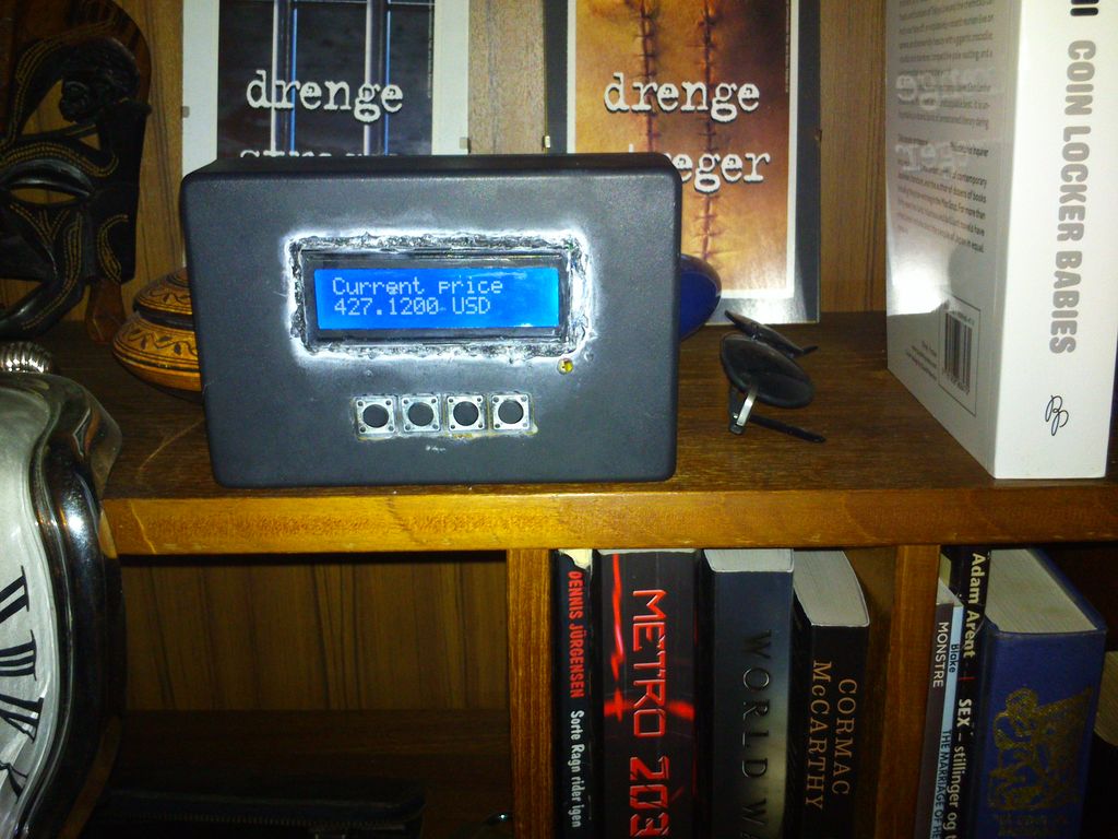
This Bitcoin Price Ticker will show the price of Bitcoins in 3 different currencies (USD, EUR & GBP), and it will update the price every minute. I fetch the price from http://coindesk.com every minute which provides an average price based on multiple markets.
I will show you how to make this entirely from scatch(well almost), building your own arduino replica with an ATmega328 microcontroller to control everything, and wrapping it all in a nice casing. The only thing we won’t make ourselves is the Adafruit CC3000. I have tried to explain all the steps as detailed as possible, without forcing you to spend hours reading. However, feel free to ask in case you have any questions or concerns.
Feel free to visit my blog/website for more projects and other things: http://www.cavaleri.dk
Have fun with this project! (I sure did)
Step 1: Gather materials
Obviously you will need a couple of things for this instructable. I will go ahead and list out the things you need, apart from the obvious work tools (soldering iron, solder, cutter bar etc).
Stuff you need:
- ATmega328P-PU (The ATmega328-PU will also work, but is a little more complicated. It will be a lot easier if you find it bootloaded with Arduino, but it is not a requirement)
- 5x 10k Ohm resistors
- 220 Ohm resistor
- 7805 Voltage Regulator 5V
- 2x 10uF capacitors
- 2x 22pF capacitors
- 16 MHz crystal
- LCD display 16×2
- 9V battery connector
- 4 switches (buttons) (I used tact switches)
- Wire (and quite a lot of it)
- Plastic box
- Prototyping board 120x80mm (I used 1½ in total)
- Adafruit CC3000 Breakout.
You can get all of the above except the CC3000 from Tayda Electronics http://www.taydaelectronics.com
The CC3000 can be found on Adafruits website http://adafruit.com but I got mine off of Ebay.
Price:
Adafruit CC3000 ~$40
Everything else: $20
Total: ~$60
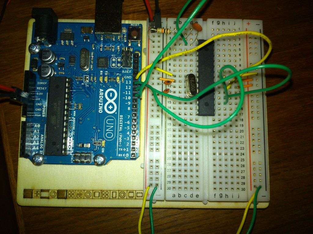
Step 2: Breadboard testing
I suggest you to build everything on a breadboard first using your Arduino (I used the Arduino UNO). Then you will be able to test if the code works, and that you are able to connect to your WIFI (if you entered the wrong credentials etc.). These images will show you how to set it up using the CC3000 shield, but it will work with the breakout as well. Simply follow the directions below to know which pin goes where.
Adafruit CC3000
As you see in the image I used a CC3000 shield I had laying around, but you will be able to use the breakout as well. If you are using the breakout your pins should look like this:
- IRQ -> Arduino 3
- VBEN -> Arduino 5
- CS -> Arduino 10
- MOSI -> Arduino 11
- MISO -> Arduino 12
- CLK -> Arduino 13
- Vin -> power
- GND – > Ground
LCD Display
On to the display. I have numbered the pins on the display from 1-16 and from the bottom up. Have a look at the image as well, in case you want to confirm the setup. As you can see on the image, I have not added any female pin headers on my CC3000 shield, which makes it a little difficult to connect the wires. Try bending the end of the wires a little to make a hook, if you are facing the same problem – it worked perfectly for me. Just make sure they do not connect underneath the shield.
- LCD 1 -> Ground
- LCD 2 -> Power
- LCD 3 -> Ground (Or you can add it to a potentiometer, which connects to power and ground. This is to alter the contrast of the screen. I however got the best result connecting it directly to ground.)
- LCD 4 -> Arduino 8
- LCD 5 -> Ground
- LCD 6 -> Arduino 7
- LCD 11 -> Arduino 6
- LCD 12 -> Arduino 4
- LCD 13 -> Arduino 9
- LCD 14 -> Arduino 2
- LCD 15 -> Power through a 220 Ohm resistor
- LCD 16 -> Ground
Switches
Lastly you add your switches/buttons over the center-rail of the breadboard. Now connect one leg to power and the other to ground through a 10k Ohm resistor. The leg opposite of the resistor goes to the Arduino pins. I did not have enough space on my small breadboard, so I had to get creative and use wires with female pin headers to connect my 4th switch to the Arduino. I used the Analog pins because we are running low on Digital pins on the arduino. I used A0, A1, A2 & A4 but you can use any you like. Just remember to alter the sketch/code accordingly!
Upload sketch
All we need to now is upload the sketch. I have commented each section of the code but most is in Danish. However, it should be easy to understand from the code itself. I will change it to a English version when I get some spare time. Feel free to make any changes, and I would love to see what you did. It is a rather long piece of code and instead of copy pasting it, I have uploaded it here.
You will need to change the details of your WIFI. The following lines need to be changed:
#define WLAN_SSID “Network_name”
#define WLAN_PASS “Passphrase”
#define WLAN_SECURITY WLAN_SEC_WPA2 (Only change this if you are not using WPA2)
The code/sketch is certainly not perfect but it really gets the job done. You are more than welcome to go ahead and make any improvements. For instance, I did not add any debouncing for the switches but only a small delay to prevent them from getting pressed multiple times on a single click. It worked perfectly for my switches but that would be a good place to start, especially if your buttons make connections even when you do not press them. Please upload your example and make a comment about it. I will definitely add any good improvements to this code.
Once everything works as it should, go ahead and clear your breadboard to make room for the next step.
 Arduino code.txt9 KB
Step 3: (optional) Bootload your ATmega328
If you do not have a ATmega328 with Arduino preloaded, you will need to program it manually. I found a very useful guide to bootload the ATmega328P-PU (you can also use the ATmega328-PU but it is slightly more complex), and I have summarized it here. Be sure to check the original tutorial in case you have any problems, if you are using the ATmega328-PU or if you are looking for a more detailed guide.
http://www.instructables.com/id/Bootload-an-ATmega328/
For this step you will need:
- ATmega328P-PU (or ATmega328-PU)
- 2x 22pf capacitors
- 0.1 uf capacitor
- 16 MHz crystal
- 220 ohm resistor
- Wires
Start by programming your Arduino as an ISP(In-System Programmer). Open the Arduino IDE and find the ArduinoISP sketch(Files->Examples->ArduinoISP). Make sure you’ve selected the UNO under the boards menu. Now go ahead and upload this sketch to your Arduino board.
For more detail: Bitcoin Price Ticker (almost) from scratch using Arduino as ISP