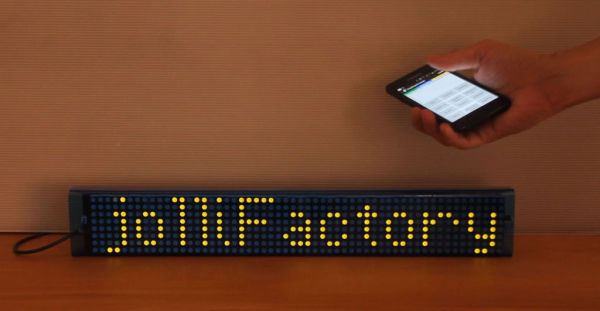
Here, we show how a 7 Bi-color 8×8 LED Matrix Scrolling Text Display is built, in which messages and commands can be sent to it via Bluetooth using an Android Smart Phone. Logically, any devices capable of sending text messages via Bluetooth may be adapted to work with the display.
To build this project, basic electronics component soldering skills and some knowledge on using the Arduino or Arduino based micro-controllers are required.
The reason for building a 7 LED Matrices long display is that it is quite adequate for ease of reading scrolling text and also because the largest tinted acrylic sheet easily available in Hobby or Art shops is 18 inches by 12 inches, which is just the right length for making the enclosure for the display as each LED matrix is around 60mm x 60mm in size.
You may view the following YouTube video to see what we are building.
Step 1: LED Matrix Driver Module Assembly
The display is built using seven of the
Bi-color (Red and Green) LED Matrix Driver Module kits from jolliFactory. Each of these modules uses two MAX7219 Display Driver ICs to drive a Bi-color LED Matrix. These ICs are excellent because they take a lot of work off the micro-controller and simplify the wiring and logic design. Moreover, there is a ready-made Arduino library for this IC. You can daisy-chain up to four of these Bi-color LED Matrices using only three output pins on the micro-controller for the interface. As our display is made up of seven Bi-color LED Matrices, we need an additional three output pins on the micro-controller to interface with the other three daisy-chained LED Matrices.
You can find this Bi-color LED Matrix Driver Module kit from
here with information on the assembly of the kit.
This kit comes with all through-hole components and someone with basic soldering skills should be able to assemble it without much difficulty.
You may view the following YouTube video on the assembly of the Bi-color LED Matrix Driver Module kit.
Step 2: Wiring
After all the kits are completed, they are connected together with the micro-controller as shown (LED Matrices are not installed for better view). Note the header for J3 is modified for the fourth LED Matrix Driver module from the right such that only VCC and GND are connected to the fifth module. This is because the first four daisy-chained modules from the right shall be driven by 3 output pins (Digital pins 2, 3 & 4) from the micro-controller and the last three daisy-chained modules shall be driven by another 3 output pins (Digital pins 5, 6 & 7).
For more detail: 7 Bi-color LED Matrix Scrolling Text Display